Seals – CIRCUTOR DISPENSER Series User Manual
Page 80
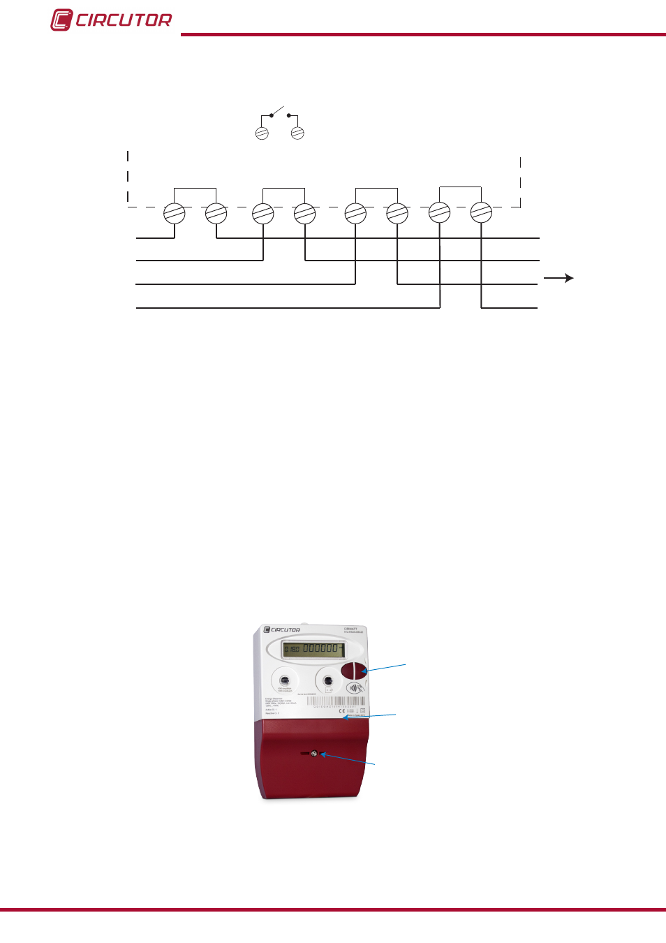
5�1�4�2�- THREE-PHASE MODEL�
3
4
6
L1
N
CARGA / LOAD
21
22
1
7
9
10
12
L2
L3
Figure 89: Connection diagram of the three-phase Dispenser Universal�
Note: The diagram also shows the terminals of the auxiliary relay, 21 and 22.
5�1�5�- SEALS
The unit can be protected with the following seals:
Sealable button, some functions can be enabled for this button, which can only be
executed if the seal is removed, showing proof that the operation was carried out.
Laboratory seal, the laboratory seal is found inside the unit, under the wire cover
lid. This seal is attached when the metrological verification process is complete.
Wire cover lid seal, this seal is attached during the installation of the unit. The pur-
pose of this seal is to prevent any form of fraud from the user.
Sealable button
Laboratory seal
Wire cover lid seal
Figure 90:Distribution of seals in the unit�
80
Dispenser Universal System
Instruction Manual