Connecting the board for i/o operations, Connectors, cables – main i/o connector – Measurement Computing USB-2527 User Manual
Page 11
USB-2527 User's Guide
Installing the USB-2527
11
Caution! Avoid redundant connections. Ensure there is no signal conflict between SCSI pins and the
associated header pin (J5, J7, and J8). Also make sure there is no conflict between theTB7 TC
connections and the SCSI and/or the 40-pin header connections.
Failure to do so could possibly cause equipment damage and/or personal injury.
Also, turn off power to all devices connected to the system before making connections. Electrical
shock or damage to equipment can result even under low-voltage conditions.
Information on signal connections
General information regarding signal connection and configuration is available in the Guide to Signal
Connections. This document is available on our web site
Caution! Always handle components carefully, and never touch connector pins or circuit components unless
you are following ESD guidelines in an appropriate ESD-controlled area. These guidelines include
using properly-grounded mats and wrist straps, ESD bags and cartons, and related procedures.
Avoid touching board surfaces and onboard components. Only handle boards by their edges. Make
sure the USB-2527 does not come into contact with foreign elements such as oils, water, and
industrial particulate.
The discharge of static electricity can damage some electronic components. Semiconductor
devices are especially susceptible to ESD damage.
Connecting the board for I/O operations
Connectors, cables
– main I/O connector
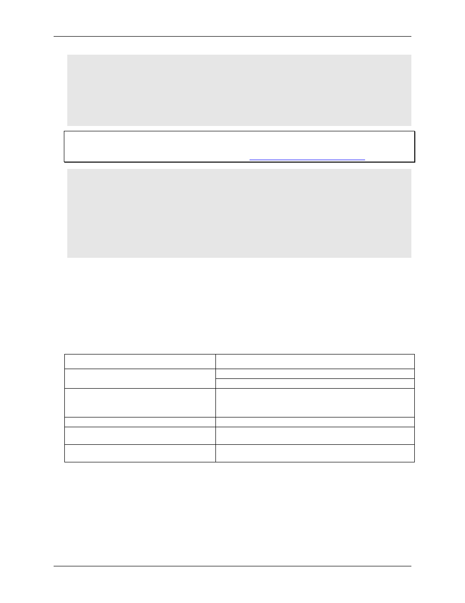
The following table lists the board connectors, applicable cables, and compatible accessory products for the
USB-2527.
Board connectors, cables, and compatible hardware
Parameter
Specification
Connector type
Main connector: 68-pin standard "SCSI type III" female connector
Auxiliary connectors: Four, 40-pin header connectors
Compatible cables — main connector
CA-68-3R — 68-pin ribbon cable; 3 feet.
CA-68-3S — 68-pin shielded round cable; 3 feet.
CA-68-6S — 68-pin shielded round cable; 6 feet
Compatible cables — 40-pin connectors
C40FF-x
Compatible accessory products using the
CA-68-3R, CA-68-3S, or CA-68-6S cables
TB-100 terminal connector
Compatible accessory products using the
C40FF-x cable
CIO-MINI40