Digital i/o, Digital input scanning, Figure 12 – Measurement Computing USB-2527 User Manual
Page 30
USB-2527 User's Guide
Functional Details
30
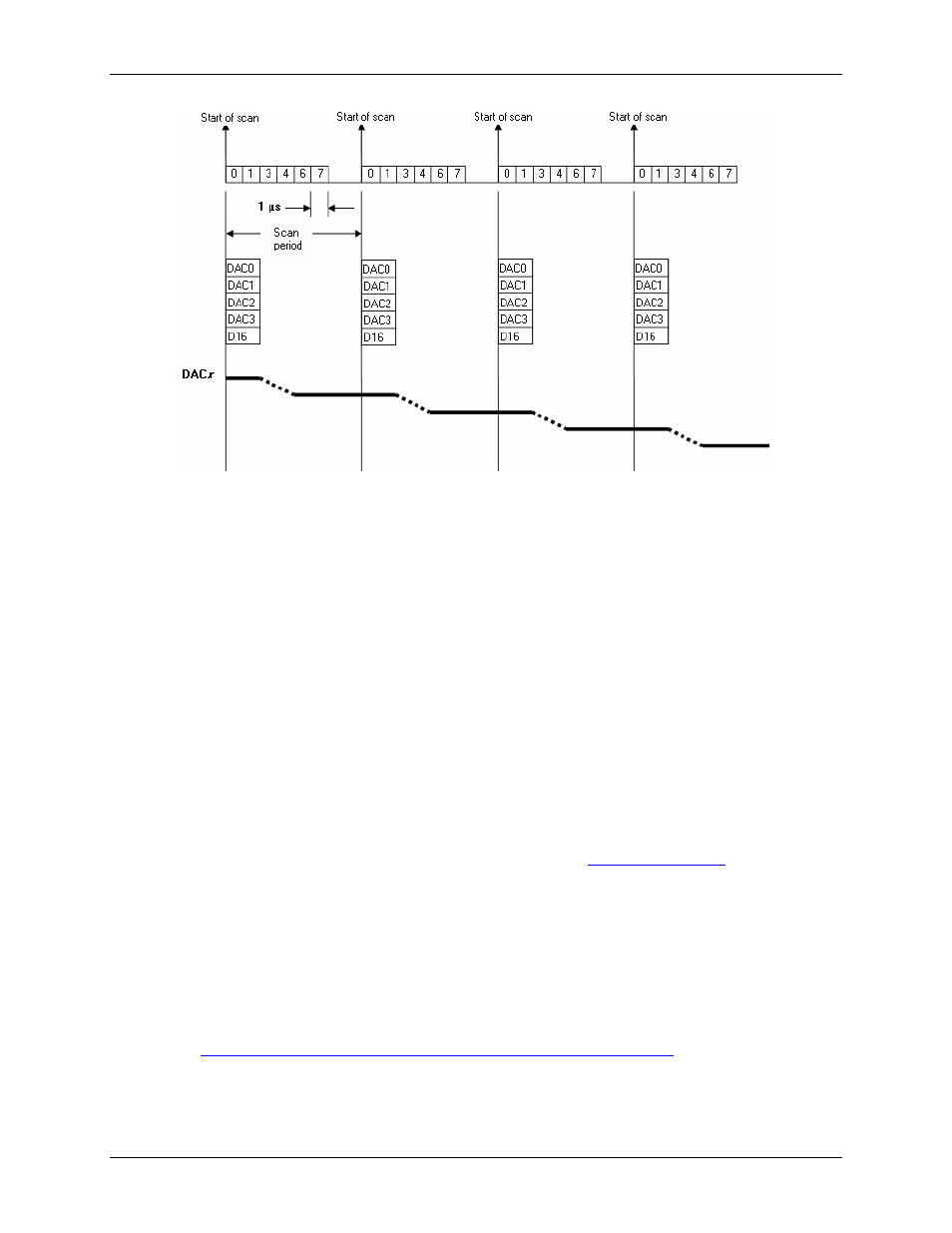
Figure 12. Analog channel scan of voltage inputs and streaming analog outputs example
This example updates all DACs and the 16-bits of digital I/O. These updates happen at the same time as the
acquisition pacer clock—also called the input scan clock. All DACs and the 16-bits of pattern digital output are
updated at the beginning of each scan.
Due to the time it takes to shift the digital data out to the DACs, plus the actual settling time of the digital-to-
analog conversion, the DACs actually take up to 4 µs after the start of scan to settle on the updated value.
The data for the DACs and pattern digital output comes from a PC-based buffer. The data is streamed across the
USB2 bus to the USB-2527.
In this example, the outputs are updated by the input scan clock, but you can also update the DACs and pattern
digital output with the output scan clock—either internally-generated or externally-applied. In this scenario, the
acquisition input scans are not synchronized to the analog outputs or pattern digital outputs.
Digital I/O
Twenty-four TTL-level digital I/O lines are included in each USB-2527. You can program digital I/O in 8-bit
groups as either inputs or outputs and scan them in several modes (see "
" below). You can
access input ports asynchronously from the PC at any time, including when a scanned acquisition is occurring.
Digital input scanning
Digital input ports can be read asynchronously before, during, or after an analog input scan.
Digital input ports can be part of the scan group and scanned along with analog input channels. Two
synchronous modes are supported when digital inputs are scanned along with analog inputs.
Refer to "
Example 4: Sampling digital inputs for every analog sample in a scan group
" on page 27 for more
information.
In both modes, adding digital input scans has no affect on the analog scan rate limitations.