Detection on an analog input, timer output updates, Using the hysteresis function – Measurement Computing USB-2527 User Manual
Page 47
USB-2527 User's Guide
Functional Details
47
Detection on an analog input, timer output updates
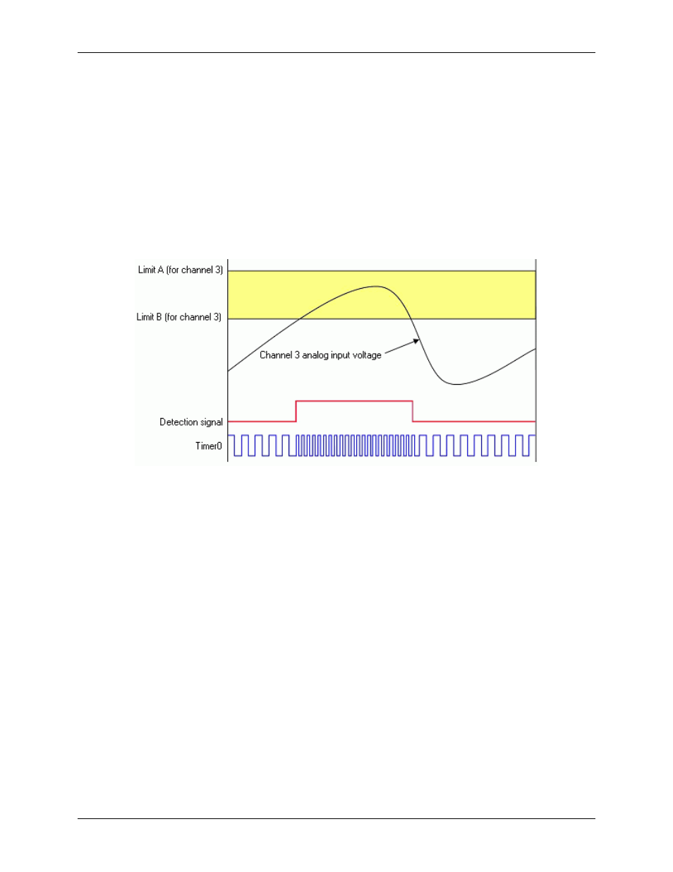
Update Mode: Update on True and False
Criteria Used: Inside window
The figure below shows how a setpoint can be used to update a timer output. Channel 3 is an analog input
channel. A setpoint is applied using update on True and False, with a criteria of inside-the-window, where the
signal value is inside the window when simultaneously less than Limit A but greater than Limit B.
Whenever the channel 3 analog input voltage is inside the setpoint window (condition True), Timer0 is updated
with one value; and whenever the channel 3 analog input voltage is outside the setpoint window (condition
False) timer0 will be updated with a second output value.
Figure 27. Timer output update on True and False
Using the hysteresis function
Update mode: N/A, the hysteresis option has a forced update built into the function
Criteria used: Window criteria for above and below the set limits
The figure below shows analog input Channel 3 with a setpoint which defines two 16-bit limits, Limit A (High)
and Limit B (Low). These are being applied in the hysteresis mode and DAC channel 0 is updated accordingly.
In this example, Channel 3's analog input voltage is being used to update DAC0 as follows:
When outside the window, low (below limit B) DAC0 is updated with 3.0 V. This update remains in effect
until the analog input voltage goes above Limit A.
When outside the window, high (above limit A), DAC0 is updated with 7.0 V. This update remains in
effect until the analog input signal falls below limit B. At that time we are again outside the limit "low" and
the update process repeats itself.
Hysteresis mode can also be done with FIRSTPORTC digital output port, or a timer output, instead of a DAC.