Debounce modes, Trigger after stable mode – Measurement Computing USB-2527 User Manual
Page 35
USB-2527 User's Guide
Functional Details
35
Debounce modes
Each channel's output can be debounced with 16 programmable debounce times from 500 ns to 25.5 ms. The
debounce circuitry eliminates switch-induced transients typically associated with electro-mechanical devices
including relays, proximity switches, and encoders.
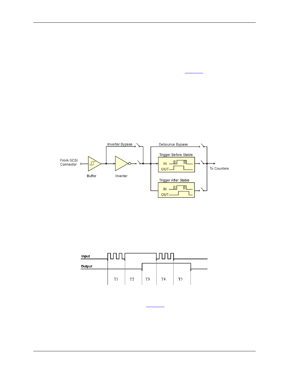
There are two debounce modes, as well as a debounce bypass, as shown in
. In addition, the signal
from the buffer can be inverted before it enters the debounce circuitry. The inverter is used to make the input
rising-edge or falling-edge sensitive.
Edge selection is available with or without debounce. In this case the debounce time setting is ignored and the
input signal goes straight from the inverter or inverter bypass to the counter module.
There are 16 different debounce times. In either debounce mode, the debounce time selected determines how
fast the signal can change and still be recognized.
The two debounce modes are trigger after stable and trigger before stable. A discussion of the two modes
follows.
Figure 14. Debounce model block diagram
Trigger after stable mode
In the trigger after stable mode, the output of the debounce module does not change state until a period of
stability has been achieved. This means that the input has an edge, and then must be stable for a period of time
equal to the debounce time.
Figure 15. Debounce module
– trigger after stable mode
The following time periods (T1 through T5) pertain to
. In trigger after stable mode, the input signal
to the debounce module is required to have a period of stability after an incoming edge, in order for that edge to
be accepted (passed through to the counter module.) The debounce time for this example is equal to T2 and T5.
T1 – In the example above, the input signal goes high at the beginning of time period T1, but never stays
high for a period of time equal to the debounce time setting (equal to T2 for this example.)