Digital input/output, Counters – Measurement Computing USB-2527 User Manual
Page 55
USB-2527 User's Guide
Specifications
55
Digital input/output
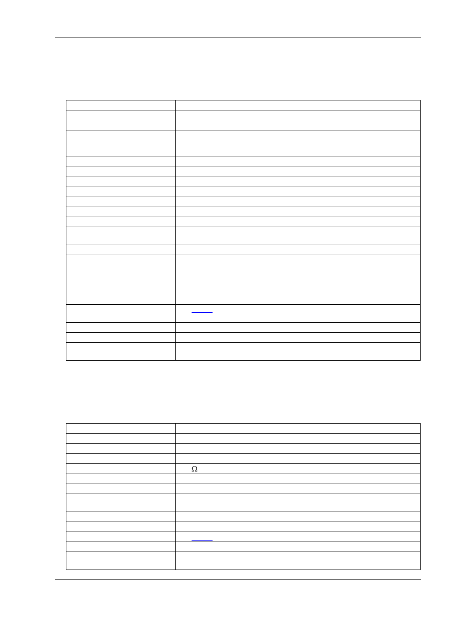
Table 5. Digital input/output specifications
Number of I/O
24
Ports
Three banks of eight.
Each port is programmable as input or output
Input scanning modes
Two programmable
Asynchronous, under program control at any time relative to input scanning
Synchronous with input scanning
Input characteristics
220 Ω series resistors, 20 pF to common
Logic keeper circuit
Holds the logic value to 0 or 1 when there is no external driver
Input protection
±15 kV ESD clamp diodes parallel
Input high
+2.0 V to +5.0 V
Input low
0 to 0.8 V
Output high
>2.0 V
Output low
<0.8 V
Output current
Output 1.0 mA per pin, sourcing more current may require a PS-9V1AEPS-2500
power supply option
Digital input pacing
Onboard clock, external input scan clock (XAPCR)
Digital output pacing
Four programmable sources:
Onboard output scan clock, independent of input scan clock
Onboard input scan clock
External output scan clock (XDPCR), independent of external input scan clock
(XAPCR)
External input scan clock (XAPCR)
Digital input trigger sources and
modes
Digital output trigger sources
Start of input scan
Sampling/update rate
4 MHz maximum (rates up to 12 MHz are sustainable on some platforms)
Pattern generation output
Two of the 8-bit ports can be configured for 16-bit pattern generation. The pattern
can also be updated synchronously with an acquisition at up to 4 MHz.
Counters
Counter inputs can be scanned based on an internal programmable timer or an external clock source.
Table 6. Counter specifications
Channels
4 independent
Resolution
32-bit
Input frequency
20 MHz maximum
Input signal range
-5 V to 10 V
Input characteristics
10 k pull-up, ±15 kV ESD protection
Trigger level
TTL
Minimum pulse width
25 ns high, 25 ns low
De-bounce times
16 selections from 500 ns to 25.5 ms, positive or negative edge sensitive, glitch
detect mode or de-bounce mode
Time-base accuracy
50 ppm (0 ° to 50 °C)
Counter read pacer
Onboard input scan clock, external input scan clock (XAPCR)
Trigger sources and modes
Programmable mode
Counter
Counter mode options
Totalize, clear on read, rollover, stop at all Fs, 16- or 32-bit, any other channel can
gate the counter