Measurement Computing USB-2527 User Manual
Page 12
USB-2527 User's Guide
Installing the USB-2527
12
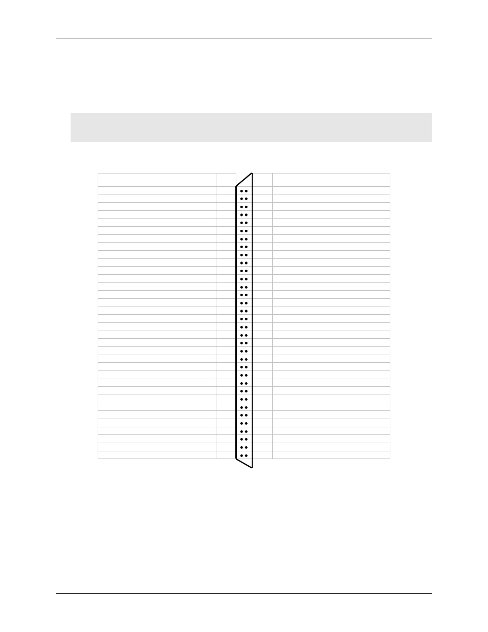
68-pin SCSI connector differential and single-ended pin outs (P5)
The 68-pin SCSI connector—labeled P5 on the board—provides 16 single-ended analog channels or eight
differential analog channels.
Caution! Avoid redundant connections. Make sure there is no signal conflict among the SCSI pins, the 40-
pin header connector pins (J5, J7, and J8), and the TB7 TC connections. Failure to do so could possibly
cause equipment damage and/or personal injury.
68-pin SCSI connector pin out (labeled P5 on the board)
16-channel single-ended mode
Signal name Pin
Pin Signal name
ACH0
68
34 ACH8
AGND
67
33
ACH1
ACH9
66
32 AGND
ACH2
65
31 ACH10
AGND
64
30 ACH3
ACH11
63
29 AGND
SGND
62
28 ACH4
ACH12
61
27 AGND
ACH5
60
26 ACH13
AGND
59
25 ACH6
ACH14
58
24 AGND
ACH7
57
23 ACH15
XDAC3
56
22 XDAC0
XDAC2
55
21 XDAC1
NEGREF (reserved for self-calibration)
54
20 POSREF (reserved for self-calibration)
GND
53
19 +5 V
A1
52
18 A0
A3
51
17 A2
A5
50
16
A4
A7
49
15 A6
B1
48
14 B0
B3
47
13 B2
B5
46
12 B4
B7
45
11 B6
C1
44
10 C0
C3
43
9 C2
C5
42
8 C4
C7
41
7 C6
GND
40
6 TTL TRG
CNT1
39
5 CNT0
CNT3
38
4 CNT2
TMR1
37
3 TMR0
GND
36
2 XAPCR
GND
35
1
XDPCR