Pin header connector pin outs, Analog channels pin out (j5 and j6) – Measurement Computing USB-2527 User Manual
Page 15
Advertising
USB-2527 User's Guide
Installing the USB-2527
15
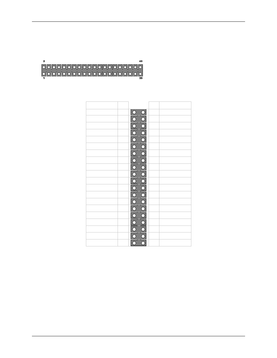
40-pin header connector pin outs
Analog channels pin out (J5 and J6)
This edge of the header is closest to the center of the USB-
2527. Pins 2 and 40 are labeled on the board silkscreen.
40-pin header connector pinout (labeled J5)
16-channel single-ended mode
Analog channel
Pin
J5
Pin Analog channel
NC
1
2
NC
NC
3
4
NC
AGND
5
6
AGND
ACH3
7
8 ACH11
ACH2
9
10 ACH10
NC
11
12 NC
NC
13
14 NC
ACH1
15
16 ACH9
ACH0
17
18 ACH8
AGND
19
20 AGND
NC
21
22 NC
NC
23
24 NC
ACH7
25
26 ACH15
ACH6
27
28 ACH14
AGND
29
30 NC
NC
31
32 NC
NC
33
34 ACH5
ACH13
35
36 ACH4
ACH12
37
38
AGND
AGND
39
40 AGND
Advertising