Setpoint configuration overview – Measurement Computing USB-2527 User Manual
Page 43
USB-2527 User's Guide
Functional Details
43
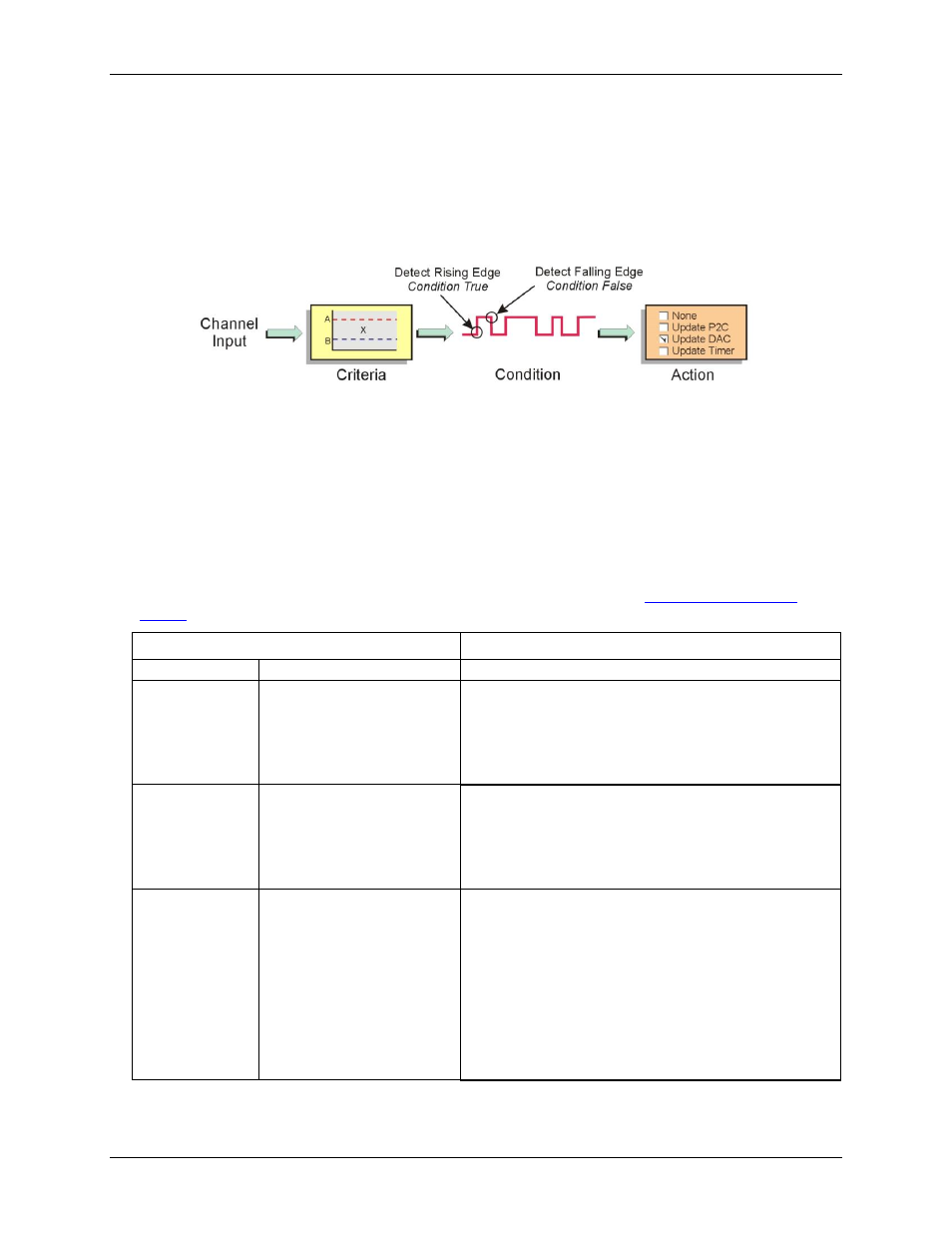
Setpoint configuration overview
You can program each detection setpoint as one of the following:
Single point referenced – Above, below, or equal to the defined setpoint.
Window (dual point) referenced – Inside or outside the window.
Window (dual point) referenced, hysteresis mode – Outside the window high forces one output (designated
Output 2; outside the window low-forces another output, designated as Output 1).
A digital detect signal is used to indicate when a signal condition is True or False—for example, whether or not
the signal has met the defined criteria. The detect signals can be part of the scan group and can be measured as
any other input channel, thus allowing real time data analysis during an acquisition.
The detection module looks at the 16-bit data being returned on a channel and generates another signal for each
channel with a setpoint applied (Detect1 for Channel 1, Detect2 for Channel 2, and so on). These signals serve
as data markers for each channel's data. It does not matter whether that data is volts, counts, or timing.
A channel's detect signal shows a rising edge and is True (1) when the channel's data meets the setpoint criteria.
The detect signal shows a falling edge and is False (0) when the channel's data does not meet the setpoint
criteria. The True and False states for each setpoint criteria are explained in the "
" section on page 45.
Criteria
– input signal is equal to X
Action - driven by condition
Compare X to:
Setpoint definition (choose one)
Update conditions:
Limit A or Limit B
Equal to A (X = A)
Below A (X < A)
Above B (X > B)
True only:
If True, then output value 1
If False, then perform no action
True and False:
If True, then output value 1
If False, then output value 2
Window* (non-
hysteresis mode)
Inside (B < X < A)
Outside: B > X; or, X > A
True only
If True, then output value 1
If False, then perform no action
True and False
If True, then output value 1
If False, then output value 2
Window*
(hysteresis mode)
Above A (X > A)
Below (B X < B) (Both
conditions are checked when
in hysteresis mode
Hysteresis mode (forced update)
If X > A is True, then output value 2 until X < B is True,
then output value 1.
If X < B is True, then output value 1 until X > A is True,
then output value 2.
This is saying:
(a) If the input signal is outside the window high, then output
value 2 until the signal goes outside the window low, and
(b) if the signal is outside the window low, then output value 1
until the signal goes outside the window high. There is no
change to the detect signal while within the window.
The detect signal has the timing resolution of the scan period as seen in the diagram below. The detect signal
can change no faster than the scan frequency (1/scan period.)