Tc connector pin out (tb7) – Measurement Computing USB-2527 User Manual
Page 63
USB-2527 User's Guide
Specifications
63
J8
Table 22. 40-pin header connector pin out (labeled J8 on the board)
Pin
Function
Pin
Function
1
+13 V (see
2
-13 V (see
3
NC
4
NC
5
AGND
6
AGND
7
XDAC0
8
XDAC2
9
XDAC1
10
XDAC3
11
AGND
12
AGND
13
SelfCal
14
SGND (low level sense - not for general use)
15
AGND
16
AGND
17
TTL TRG
18
XDPCR (output scan clock)
19
XAPCR (input scan clock)
20
GND (digital)
21
GND (digital)
22
GND (digital)
23
NC
24
NC
25
+5 V (see
26
AUX PWR (output - reserved)
27
NC
28
NC
29
NC
30
NC
31
NC
32
NC
33
NC
34
NC
35
NC
36
NC
37
NC
38
NC
39
NC
40
NC
Note 7:
5 V output, ±20% tolerance, 2mA USB powered, 10mA using external power.
Note 8:
±13 V outputs, ±10% tolerance, 1 mA USB powered, 5 mA using external power.
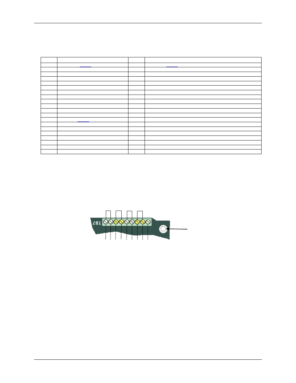
TC connector pin out (TB7)
Figure 33. TC terminal pin out (labeled TB7)
AGND
ACH0
+
ACH8
(
-)
ACH1
+
ACH9
(
-)
ACH2
+
ACH10
(
-)
ACH3
+
ACH11
(
-)
TC CH
3
TC CH
2
TC CH
1
TC
CH
0
Standoff