Detecting setpoints on a totalizing counter, Detection setpoint details, Controlling analog, digital, and timer outputs – Measurement Computing USB-2527 User Manual
Page 49
USB-2527 User's Guide
Functional Details
49
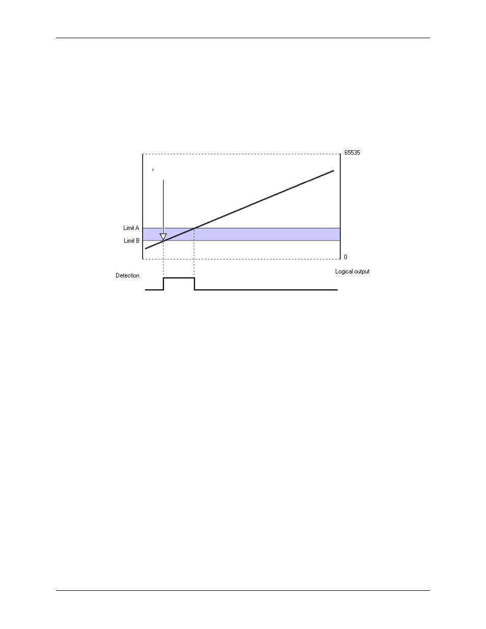
Detecting setpoints on a totalizing counter
In the following figure, Channel 1 is a counter in totalize mode. Two setpoints define a point of change for
Detect 1 as the counter counts upward. The detect output is high when inside the window (greater than Limit B
(the low limit) but less than Limit A (the high limit).
In this case, the Channel 1 setpoint is defined for the 16 lower bits of channel 1's 32-bit value. The
FIRSTPORTC digital output port could be updated on a True condition (the rising edge of the detection signal).
You can also update one of the DAC output channels or timer outputs with a value.
Figure 30. Channel 1 in totalizing counter mode, inside the window setpoint
Detection setpoint details
Controlling analog, digital, and timer outputs
You can program each setpoint with an 8-bit digital output byte and corresponding 8-bit mask byte. When the
setpoint criteria is met, the FIRSTPORTC digital output port can be updated with the given byte and mask. You
can also program each setpoint with:
a 16-bit DAC update value, and any one of the four DAC outputs can be updated in real time
a timer update value
In hysteresis mode, each setpoint has two forced update values. Each update value can drive one DAC, one
timer, or the FIRSTPORTC digital output port. In hysteresis mode, the outputs do not change when the input
values are inside the window. There is one update value that gets applied when the input values are less than the
window and a different update value that gets applied when the input values are greater than the window.
Update on True and False uses two update values. The update values can drive DACs, FIRSTPORTC, or timer
outputs.
FIRSTPORTC digital outputs can be updated immediately upon setpoint detection. This is not the case for
analog outputs, as these incur another 3 µs delay. This is due to the shifting of the digital data out to the D/A
converter which takes 1 µs, plus the actual conversion time of the D/A converter, i.e., another 2µs (worst case).
Going back to the above example, if the setpoint for analog input Channel 2 required a DAC update it would
occur 5µs after the ADC conversion for Channel 2, or 6µs after the start of the scan.
When using setpoints to control any of the DAC outputs, increased latencies may occur if attempting to stream
data to DACs or pattern digital output at the same time. The increased latency can be as long as the period of
At this point you can update FIRSTPORTC or DACs