Trigger sources and modes, Frequency/pulse generators, Power consumption – Measurement Computing USB-2527 User Manual
Page 57: Table 8
USB-2527 User's Guide
Specifications
57
Trigger sources and modes
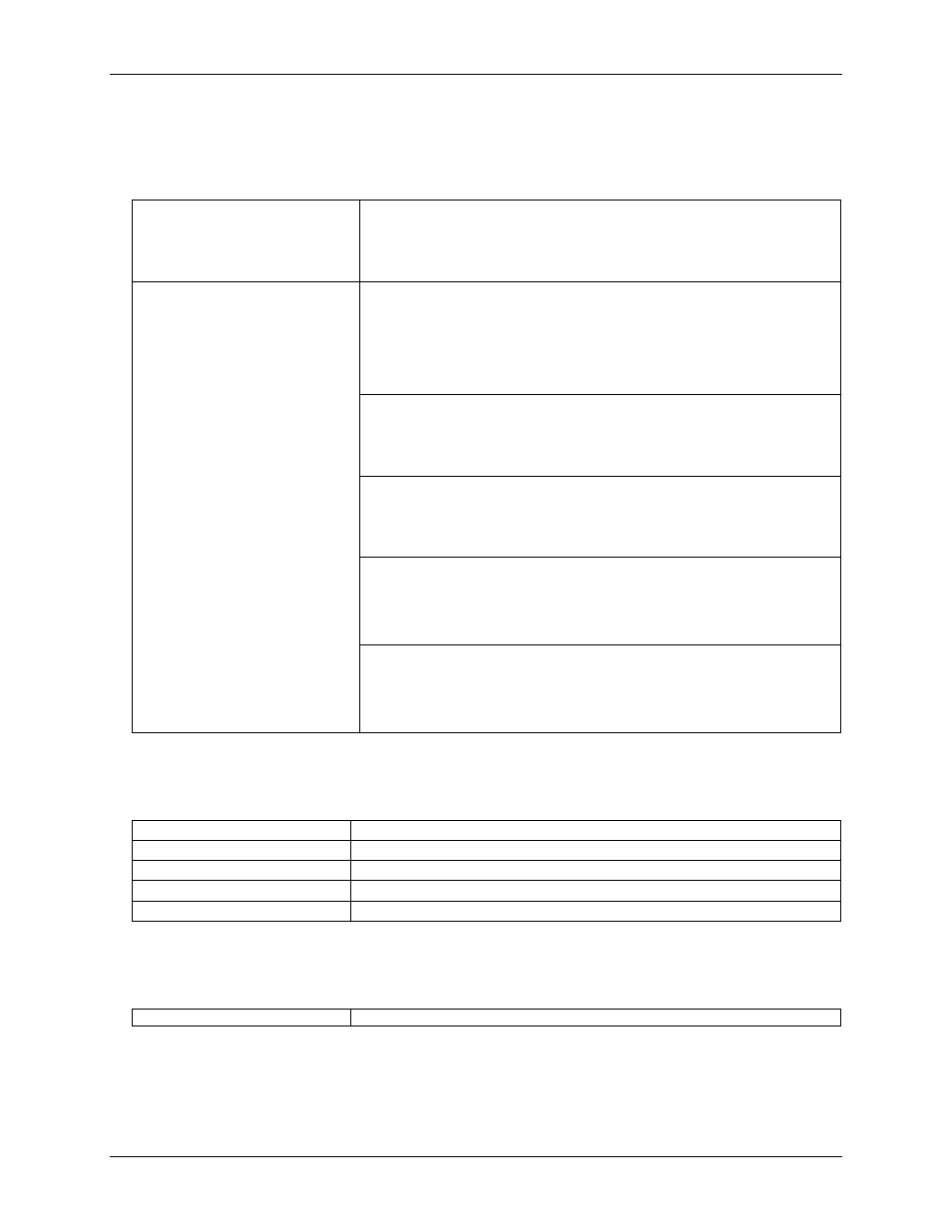
Table 8. Trigger sources and modes
Input scan trigger sources
Single channel analog hardware trigger
Single channel analog software trigger
External-single channel digital trigger (TTL TRG input)
Digital pattern trigger
Counter/totalizer trigger
Input scan triggering modes
Single channel analog hardware trigger:
The first analog input channel in the scan is the analog trigger channel
Input signal range: -10 V to +10 V maximum
Trigger level: Programmable (12-bit resolution)
Latency: 350 ns typical
Accuracy: ±0.5% of reading, ±2 mV offset maximum
Noise: 2 mV RMS typical
Single channel analog software trigger:
The first analog input channel in the scan is the analog trigger channel
Input signal range: Anywhere within range of the trigger channel
Trigger level: Programmable (16-bit resolution)
Latency: One scan period (maximum)
External-single channel digital trigger (TTL trigger input):
Input signal range: -15 V to +15 V maximum
Trigger level: TTL level sensitive
Minimum pulse width: 50 ns high, 50 ns low
Latency: One scan period maximum
Digital Pattern Triggering
8 or 16 bit pattern triggering on any of the digital ports. Programmable for
trigger on equal, not equal, above, or below a value. Individual bits can be
masked for ―don’t care‖ condition.
Latency: One scan period, maximum
Counter/Totalizer Triggering
Counter/totalizer inputs can trigger an acquisition. User can select to trigger on
a frequency or on total counts that are equal, not equal, above, or below a value,
or within/outside of a window rising/falling edge.
Latency: One scan period, maximum
Frequency/pulse generators
Table 9. Frequency/pulse generator specifications
Channels
2 x 16-bit
Output waveform
Square wave
Output rate
1 MHz base rate divided by 1 to 65535 (programmable)
High-level output voltage
2.0 V minimum @ -1.0 mA, 2.9 V minimum @ -400 µA
Low-level output voltage
0.4 V maximum @ 400 µA
Power consumption
Table 10. Power consumption specifications (Note 5)
Power consumption (per board)
3000 mW