Pin header connector pin outs – Measurement Computing USB-2527 User Manual
Page 60
USB-2527 User's Guide
Specifications
60
Table 17. 68-pin SCSI connector pin out (labeled P5 on the board)
8-channel differential mode
Pin
Function
Pin
Function
68
ACH0 HI
34
ACH0 LO
67
AGND
33
ACH1 HI
66
ACH1 LO
32
AGND
65
ACH2 HI
31
ACH2 LO
64
AGND
30
ACH3 HI
63
ACH3 LO
29
AGND
62
SGND (low level sense - not for general use)
28
ACH4 HI
61
ACH4 LO
27
AGND
60
ACH5 HI
26
ACH5 LO
59
AGND
25
ACH6 HI
58
ACH6 LO
24
AGND
57
ACH7 HI
23
ACH7 LO
56
XDAC3
22
XDAC0
55
XDAC2
21
XDAC1
54
NEGREF (reserved for self-calibration)
20
POSREF (reserved for self-calibration)
53
GND
19
+5 V (see
52
A1
18
A0
51
A3
17
A2
50
A5
16
A4
49
A7
15
A6
48
B1
14
B0
47
B3
13
B2
46
B5
12
B4
45
B7
11
B6
44
C1
10
C0
43
C3
9
C2
42
C5
8
C4
41
C7
7
C6
40
GND
6
TTL TRG
39
CNT1
5
CNT0
38
CNT3
4
CNT2
37
TMR1
3
TMR0
36
GND
2
XAPCR (input scan clock)
35
GND
1
XDPCR (output scan clock)
Note 6:
5 V output, ±20% tolerance, 2mA USB powered, 10mA using external power.
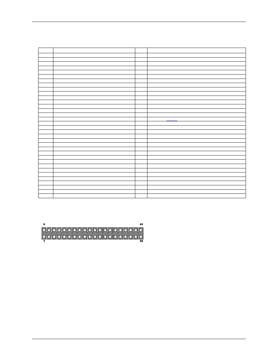
40-pin header connector pin outs
This edge of the header is closest to the center of the USB-
2527. Pins 2 and 40 are labeled on the board silkscreen.