Encoder mode – Measurement Computing USB-2527 User Manual
Page 38
USB-2527 User's Guide
Functional Details
38
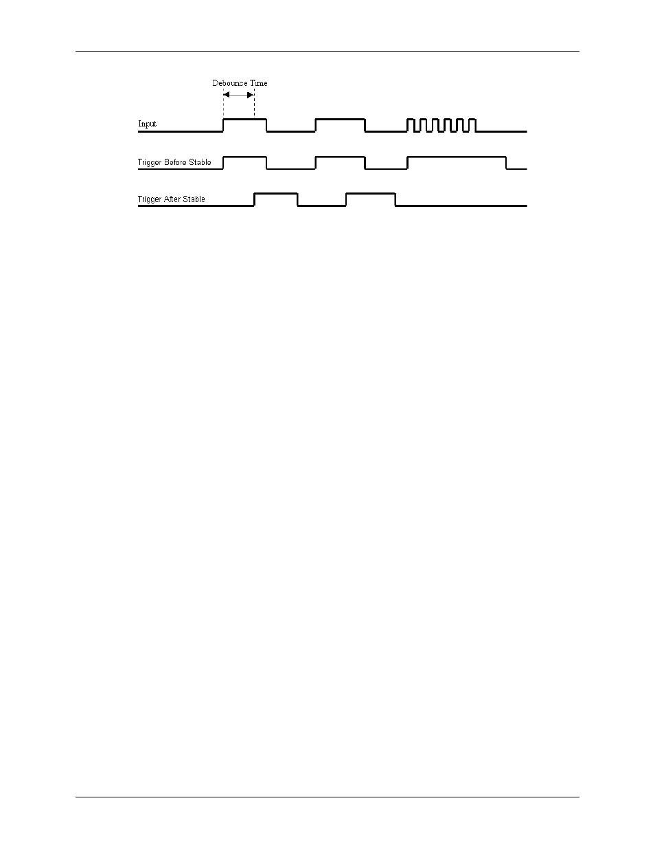
Figure 19. Optimal debounce time for trigger after stable mode
Encoder mode
Rotary shaft encoders are frequently used with CNC equipment, metal-working machines, packaging
equipment, elevators, valve control systems, and in a multitude of other applications in which rotary shafts are
involved.
The encoder mode allows the USB-2527 to make use of data from optical incremental quadrature encoders. In
encoder mode, the USB-2527 accepts single-ended inputs. When reading phase A, phase B, and index Z
signals, the USB-2527 provides positioning, direction, and velocity data.
The USB-2527 can receive input from up to two encoders.
The USB-2527 supports quadrature encoders with a 16-bit (counter low) or a 32-bit (counter high) counter,
20 MHz frequency, and X1, X2, and X4 count modes. With only phase A and phase B signals, two channels are
supported; with phase A, phase B, and index Z signals, 1 channel is supported. Each input can be debounced
from 500 ns to 25.5 ms (total of 16 selections) to eliminate extraneous noise or switch induced transients.
Encoder input signals must be within -5 V to +10 V and the switching threshold is TTL (1.3V).
Quadrature encoders generally have three outputs: A, B, and Z. The A and B signals are pulse trains driven by
an optical sensor inside the encoder. As the encoder shaft rotates, a laminated optical shield rotates inside the
encoder. The shield has three concentric circular patterns of alternating opaque and transparent windows
through which an LED shines. There is one LED and one phototransistor for each of the concentric circular
patterns. One phototransistor produces the A signal, another phototransistor produces the B signal and the last
phototransistor produces the Z signal. The concentric pattern for A has 512 window pairs (or 1024, 4096, etc.)
When using a counter for a trigger source, use a pre-trigger with a value of at least 1. Since all counters start at
zero with the initial scan, there is no valid reference in regard to rising or falling edge. Setting a pre-trigger to
1 or more ensures that a valid reference value is present, and that the first trigger is legitimate.