Functional details, Usb-2527 components – Measurement Computing USB-2527 User Manual
Page 22
Advertising
22
Chapter 3
Functional Details
This chapter contains detailed information on all of the features available from the board, including:
a diagram and explanations of physical board components
a functional block diagram
information on how to use the signals generated by the board
diagrams of signals using default or conventional board settings
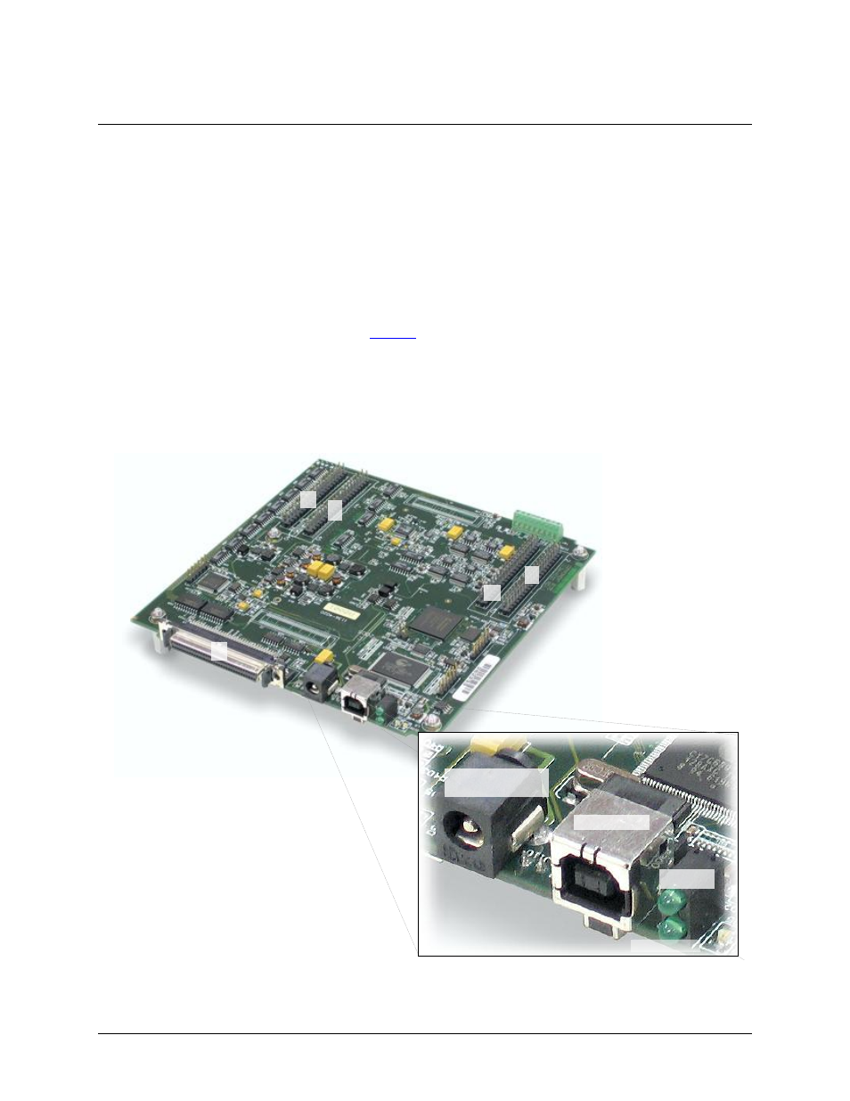
USB-2527 components
These USB-2527 components are shown in
One USB port
One external power connector
One 68-pin SCSI connector
Four 40-pin headers (J5, J6, J7, and J8)
One four-channel TC screw terminal block
Two LED indicators (USB and power)
Figure 6. USB-2527 components
J5
J6
J8
J7
TB7
P5
USB LED
USB 2.0 port
External power
supply connector
Power LED
Advertising