Measurement Computing USB-2527 User Manual
Page 46
USB-2527 User's Guide
Functional Details
46
Channel Condition
State of detect
signal
Action
5
Below limit A (for
channel 5)
True
When channel 5 analog input voltage is below the limit
A, update DAC1 with output value 0.0 V.
False
When the above stated condition is false, update DAC1
with the Output Value of minus 1.0 V.
4
Within window (between
limit A and limit B) for
channel 4
True
When Channel 4's analog input voltage is within the
window, update FIRSTPORTC with 70h.
False
When the above stated condition is False (channel 4
analog input voltage is outside the window), update
FIRSTPORTC with 30h.
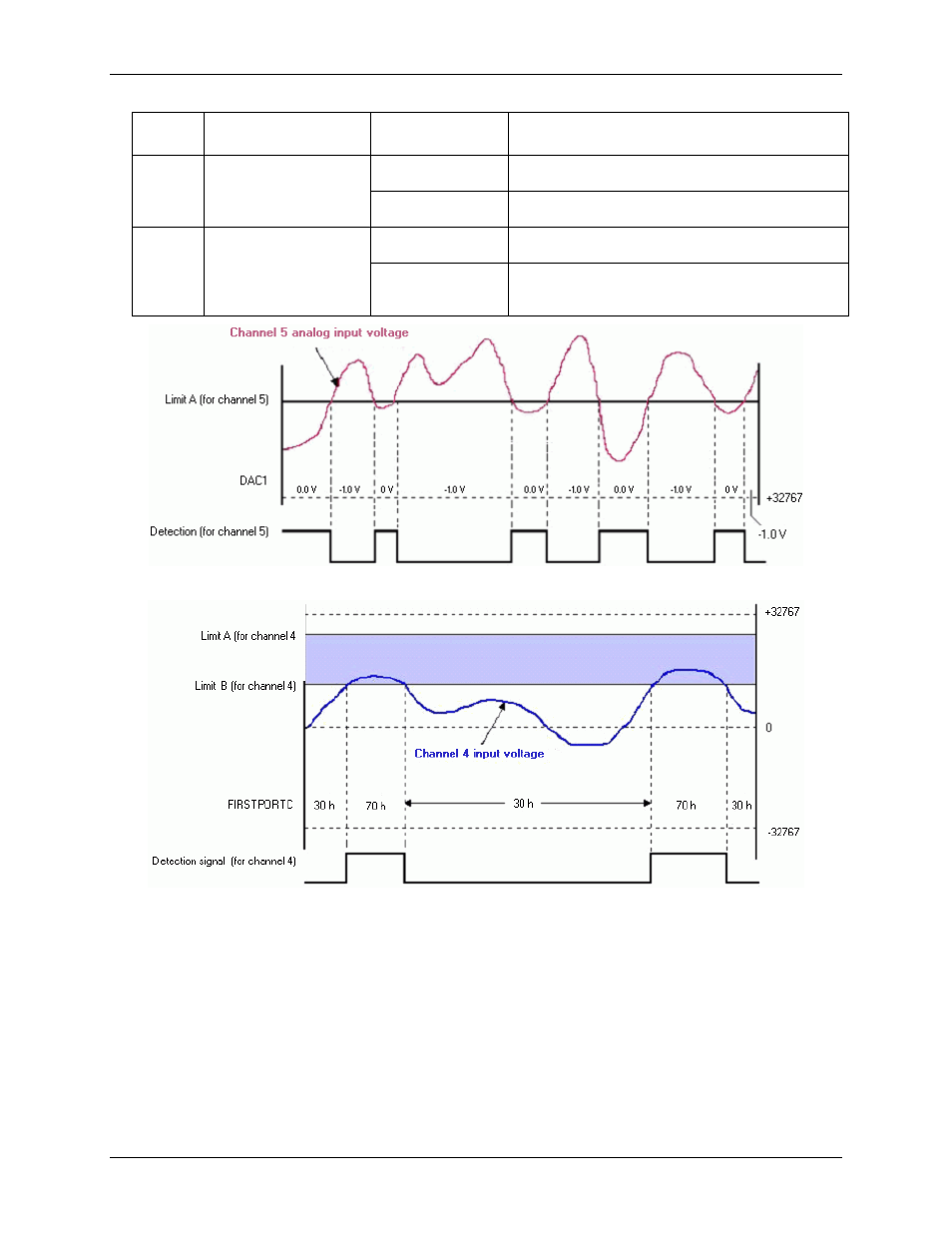
Figure 26. Analog inputs with setpoints update on True and False
In the channel 5 example, the setpoint placed on analog Channel 5 updated DAC1 with 0.0 V. The update
occurred when channel 5's input was less than the setpoint (limit A). When the value of channel 5's input was
above setpoint limit A, the condition of <A was false and DAC1 was then updated with minus1.0V.
You can program control outputs programmed on each setpoint, and use the detection for channel 4 to update
the FIRSTPORTC digital output port with one value (70 h in the example) when the analog input voltage is
within the shaded region and a different value when the analog input voltage is outside the shaded region (30 h
in the example).