Setpoint configuration, Set high limit, Set low limit – Measurement Computing USB-2527 User Manual
Page 44: Set criteria
USB-2527 User's Guide
Functional Details
44
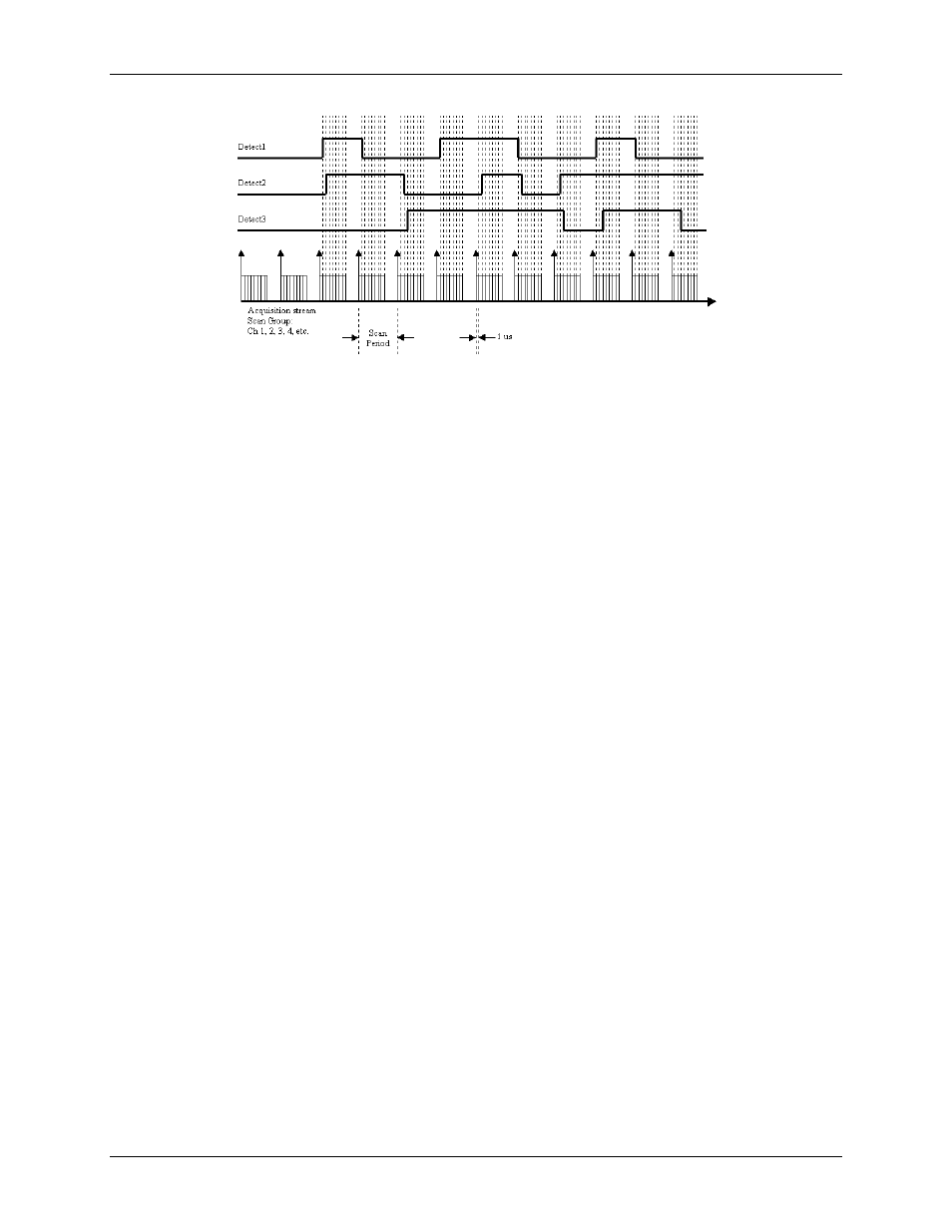
Figure 25. Example diagram of detection signals for channels 1, 2, and 3
Each channel in the scan group can have one detection setpoint. There can be no more than 16 total setpoints
total applied to channels within a scan group.
Detection setpoints act on 16-bit data only. Since the USB-2527 has 32-bit counters, data is returned 16-bits at a
time. The lower word, the higher word, or both lower and higher words can be part of the scan group. Each
counter input channel can have one detection setpoint for the counter's lower 16-bit value and one detection
setpoint for the counter's higher 16-bit value.
Setpoint configuration
You program all setpoints as part of the pre-acquisition setup, similar to setting up an external trigger. Since
each setpoint acts on 16-bit data, each has two 16-bit compare values: a high limit (limit A) and a low limit
(limit B). These limits define the setpoint window.
There are several possible conditions (criteria) and effectively three update modes, as explained in the following
configuration summary.
Set high limit
You can set the 16-bit high limit (limit A) when configuring the USB-2527 through software.
Set low limit
You can set the 16-bit low limit (limit B) when configuring the USB-2527 through software.
Set criteria
Inside window: Signal is below 16-bit high limit and above 16-bit low limit.
Outside window: Signal is above 16-bit high limit, or below 16-bit low limit.
Greater than value: Signal is above 16-bit low limit, so 16-bit high limit is not used.
Less than value: Signal is below 16-bit high limit, so 16-bit low limit is not used.
Equal to value: Signal is equal to 16-bit high limit, and limit B is not used.
The equal to mode is intended for use when the counter or digital input channels are the source channel.
You should only use the equal to16-bit high limit (limit A) mode with counter or digital input channels as
the channel source. If you want similar functionality for analog channels, then use the inside window mode
Hysteresis mode: Outside the window, high forces output 2 until an outside the window low condition
exists, then output 1 is forced. Output 1 continues until an outside the window high condition exists. The
cycle repeats as long as the acquisition is running in hysteresis mode.