Measurement Computing USB-2527 User Manual
Page 40
USB-2527 User's Guide
Functional Details
40
Differential applications are not supported.
For single-ended applications:
Connect signals A, B, and Z to the counter inputs on the USB-2527.
Connect each encoder ground to GND.
You can also connect external pull-up resistors to the USB-2527 counter input terminal blocks by placing a
pull-up resistor between any input channel and the encoder power supply. Choose a pull-up resistor value based
on the encoder's output drive capability and the input impedance of the USB-2527. Lower values of pull-up
resistors cause less distortion, but also cause the encoder's output driver to pull down with more current.
Connecting external pull-up resistors to the USB-2527
For open-collector outputs, you can connect external pull-up resistors to the USB-2527's counter input terminal
blocks. You can place a pull-up resistor between any input channel and the provided +5 V power supply.
Choose a pull-up resistor value based on the encoder's output drive capability and the input impedance of the
USB-2527. Lower values of pull-up resistors cause less distortion but also cause the encoder's output driver to
pull down with more current.
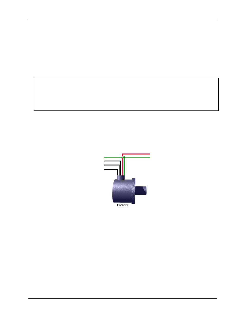
Wiring to one encoder
: Figure 21 shows the connections for one encoder to a module.
The following figure illustrates connections for one encoder to a 68-pin SCSI connector on a USB-2527.
The "A" signal must be connected to an even-numbered channel and the associated "B" signal must be
connected to the next [higher] odd-numbered channel. For example, if "A" were connected to CTR0, "B" would
be connected to CTR1.
Figure 21. Encoder connections to pins on the SCSI connector*
* Connections can instead be made to the associated screw-terminals of a connected TB-100 terminal connector
option.
The "A" signal must be connected to an even-numbered channel and the associated "B" signal must be
connected to the next higher odd-numbered channel. For example, if "A" were connected to counter 0, then "B"
would be connected to counter 1.
If the encoder stops rotating, but is vibrating (due to it being mounted to a machine), you can use the debounce
feature to eliminate false edges. Choose an appropriate debounce time and apply it to each encoder channel.
Refer to the Debounce modes section in the Functional Details chapter in this manual for additional information
regarding debounce times.
You can get the relative position and velocity from the encoder. However, during an acquisition, you cannot get
data that is relative to the Z-position until the encoder locates the Z-reference.
Ground (to Digital Common
pin 35, 36, 40)
Counter 0 (CNT0, pin 5)
– To Encoder “A”
Counter 1 (CNT1, pin 39)
– To Encoder “B”
Counter 2 (CNT2, pin 4)
– To Encoder “Z”
+5 VDC, pin 19
To ground
(of external power source