Indicator panel, Figure 8: sf-2050 indicator panel – NavCom SF-2050 Rev.G User Manual
Page 39
SF-2050 User Guide – Rev. G
9 Pulse delay, default 0mS, range 0 – 999mS
9 Rising or Falling Edge Synchronization
A BNC female connector provides the 1PPS output
pulse. A 3ft (0.9m) long, BNC male to BNC male
cable (P/N 94-310050-3003) is available from
NavCom.
Indicator Panel
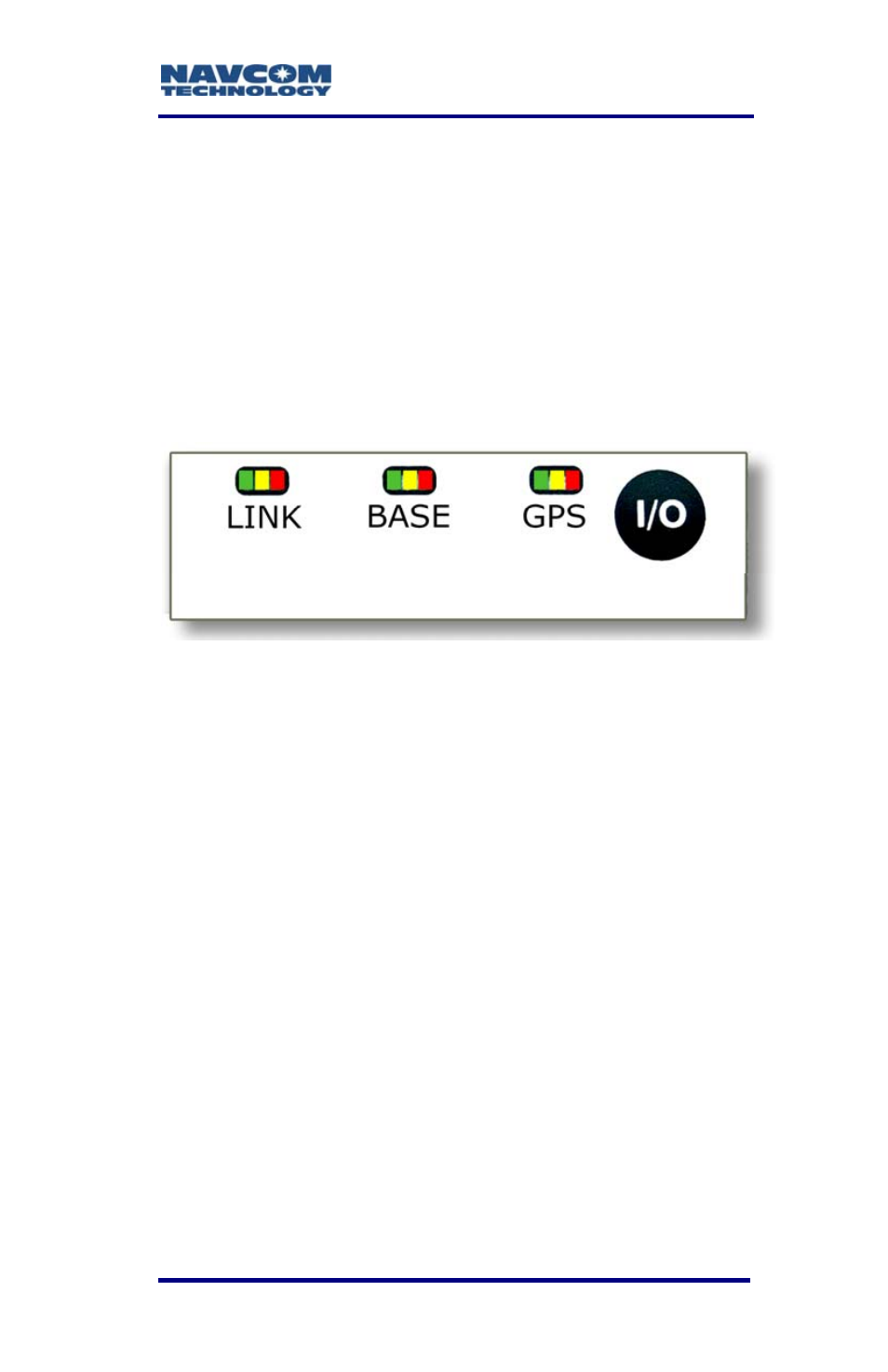
Figure 8: SF-2050 Indicator Panel
The indicator panel provides a quick status view of
the StarFire™ signal strength, base station correction
type, GPS navigation/operating mode, and the On/Off
(I/O) switch, respectively. Each set of indicators has
three LEDs.
To power the unit on or off, depress the I/O switch for
more than 3 seconds. All LEDs illuminate for a period
of 3-5 seconds during power-up of the GPS sensor.
Link
LEDs
The Link LEDs are software
configurable via the x3f proprietary
command. Only the factory default
configuration is described here.
2-37