Gps antenna connector, Figure 14: communication port connections – NavCom SF-2050 Rev.G User Manual
Page 51
SF-2050 User Guide – Rev. G
Refer to the Technical Reference Manual for
available port configuration settings.
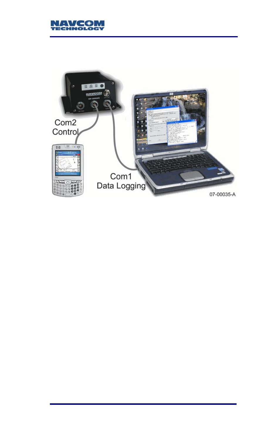
Figure 14: Communication Port Connections
GPS Antenna Connector
The connector used on the SF-2050 is a TNC female,
labeled GPS on the front panel of the sensor as
shown in Figure 5.
The SF-2050M and SF-2050G GPS
connector provides 5 VDC, 50mA max
power the antenna preamplifier. The
SF-2050-R GPS connector provides
4.25 to 4.75 VDC, 50mA max power
the GPS antenna preamplifier, and the
StarFire™ connector provides 5.0
VDC, 50mA max power the StarFire™
only antenna preamplifier. Do not
disconnect the antenna when the GPS
unit is powered on.
The system is supplied with 12ft (3.6m) of RG58/U
cable (P/N 94-310058-3012). The cable is fitted with
3-49