D event input configuration, Event input configuration, Figure d1: event cable wiring diagram – NavCom SF-2050 Rev.G User Manual
Page 83: Table d1: event wiring connections, D ...................... event input configuration
SF-2050 User Guide – Rev. G
D ...................... Event Input Configuration
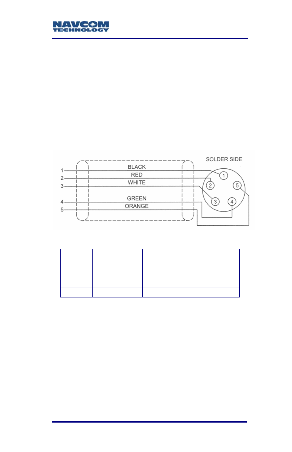
Figure D1 details the wiring of the Event/Can cable
assembly NavCom part number P/N 94-310062-
3003.
Refer to Chapter 2, Event for detailed electrical
specifications.
Table D1 details the wiring configuration required for
Event-Hi, and Event-Lo pulse sensing.
Figure D1: Event Cable Wiring Diagram
Pin #
Signal
Name
Event Sync Wiring
1
Event Lo
Tie Event-Hi to Ground
2
Event Hi
Tie Event-Lo to Ground
3 Ground
N/A
Table D1: Event Wiring Connections
Once the cable is wired to correspond with the event
pulse requirements, configure the receiver to output
the message containing a time mark, referenced to
the time kept within the receiver, indicating when the
event is sensed (xB4).
The Event Input can be triggered on the Rising or
Falling edge of the input pulse. Configuration is
possible thru the StarUtil program. Select Receiver >
Setup > PPS and Event Latch from the menu bar.
D-81