Overview, Parts and descriptions, Rne modular controller field technical guide 10 – Orion System RNE Modular Controller User Manual
Page 10
OVERVIEW
RNE Modular Controller Field Technical Guide
10
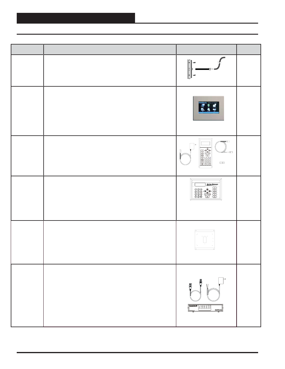
Parts and Descriptions
PART NO:
PART DESCRIPTION
ILLUSTRATION
PAGE NO.
OE290
Static Pressure Pick-up Tube
Used with OE271 Static Pressure Sensor for static pressure sensing applica-
tions. Includes: Static Pressure Pick-up Tube with 1 ft. length of FRP tubing,
gasketed mounting bracket, and screws.
Page 18
OE392-10
System Manager TS II Operator Interface
The System Manager TS II provides a direct, graphic-enhanced, menu-driven
link to enable the system operator to view the status and adjust the setpoints
of any controller on the RNE control system. The System Manager TS II is
equipped with a 4.3” 480 x 272 WQVGA RGB TFT LCD Touch Screen
Display. The System Manager TS is furnished with hardware for fl ush
mounting into hollow drywall or surface mounting on concrete brick or
plaster surfaces. Includes: System Manager TS with 12 ft. long pigtail cable
assembly.
See the
System
Manager
Touch
Screen II
Technical
Guide
OE391-12
Modular Service Tool SD
Includes: Modular Service Tool SD, power supply, communication cables,
adapter plug, and (4) AA batteries. Used to program and monitor all Orion
controllers.
Mode
Selection
6
5
4
7
0
8
1
3
2
9
-
See the RNE
Controller
Operator
Interfaces
SD
Technical
Guide
OE392-12
Modular System Manager SD
Includes: Modular System Manager SD with 4 Gigabyte SD card and 12 ft.
long pigtail cable assembly. Used to program and monitor all Orion
controllers. Designed for hollow core wall mounting. When System Manager
is to be mounted on a solid wall (concrete), you will also need to order the
solid wall mounting bracket below. Modular System Manager and
communication cables.
See the RNE
Controller
Operator
Interfaces
SD
Technical
Guide
EB101505
Solid Wall Mounting Bracket for Modular System
Manager SD
Includes: 22 gauge galvanized sheet metal mounting bracket with mounting
holes and wire routing opening. Dimensions are 9.25″W x 8.00″H x 0.50″DP.
The Wall Mounting Bracket provides wiring clearance between the System
Manager and the wall mounting surface when the System Manager is to be
mounted on a concrete or other solid wall surface. Not for use with System
Manager TS.
N/A
OE361-13
CommLink 5 Communications Interface
The CommLink 5 connects to your control system using a USB computer
connection to provide direct on-site communications with the control system
from a computer with the Prism 2 software installed. For remote communica-
tions, see OE415-02 IP Module Kit.
Includes: CommLink 5, 6 ft. long USB cable, and 120/24 VAC power supply.
Required on all networked systems or if direct computer or remote computer
connection is required. Connects to your computer’s USB 1.1 or 2.1 port.
Prism 2 computer front-end software must be installed on the direct connect-
ed or remote connected computer in order to communicate with your system.
STATUS
See the
CommLink
5 Technical
Guide