Installation and wiring, Rne modular controller field technical guide, Warning – Orion System RNE Modular Controller User Manual
Page 27: 24 vac gnd, Vcm-x expansion module
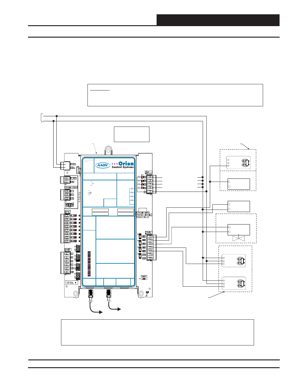
RNE Modular Controller Field Technical Guide
INSTALLATION AND WIRING
27
The expansion modules can be used individually or together to provide
the required inputs and outputs for your specifi c applications.
The VCM-X Expansion Module must be connected to 24 VAC as shown
in the wiring diagram below. Please see Table 1 on page 17 for correct
VA requirements to use when sizing the transformer(s) used for power-
ing the expansion module.
VCM-X Expansion Module Output Wiring for the RNE Controller
Figure 18: OE333-23-EM – VCM-X Expansion Module for RNE Output Wiring
24 VAC
GND
10 VA Minimum
Power Required For
VCM-X Expansion
Module
WARNING!!
Observe Polarity! All boards must be wired with GND-to-GND and 24VAC-to-24VAC. Failure to observe polarity will result in
damage to one or more of the boards. Expansion Modules must be wired in such a way that the expansion modules and the
controller are always powered together. Loss of power to the expansion module will cause the controller to become inoperative
until power is restored to the expansion module.
COM
COM
COM
+
+
+
Modulating Heating
(0 to 10 VDC
Or 2 to 10 Input)
Building Pressure
Relief Fan VFD
Building Pressure Control
Damper Actuator
Modulating Chilled Water Valve
(0 To 10 Or 2 To 10 VDC Input)
Return Air Bypass
Damper Actuator
(0-10 VDC)
Return Air
Damper Actuator
(0-10 VDC)
Configurable Relay Output #1
R1
R2
R3
R4
Configurable Relay Output #2
Configurable Relay Output #3
Configurable Relay Output #4
Belimo Actuator Wiring
Shown. Consult Factory
For Other Manufacturer
Wiring Instructions
Either A Building Pressure
Damper Actuator Or a
Building Pressure Relief
Fan VFD Can Be Used,
3 Y1
3 Y1
3 Y1
2 +
2 +
2 +
1 COM
1 COM
1 COM
Relay Output Contacts R1 Through R4 May
Be User-Configured For The Following:
Note:
-
1 - Heating Stages
2 - Cooling Stages
3 - Warm-up Mode Command (VAV Boxes)
4 - Reversing Valve (Heat Pumps)
5 - Reheat Control (Dehumidification)
6 - Exhaust Fan Interlock
7 - Preheater For Low Ambient Protection
8 - Alarm
9 - Override
10 - Occupied
11 - OA Damper
12 - Heat Wheel
13 - Emergency Heat
A Total Of 20 Relays Are Available By
Adding Relay Expansion Modules. All
Expansion Module Relay Outputs Are User
Configurable As Listed Above.
Note:
All Relay Outputs Are Normally
Open And Rated For 24 VAC
Power Only. 1 Amp Maximum
Load.
VCM-X Expansion
Module
A 1
O
AO2
AO3
AO4
AO5
RELAY CONTACT
RATING IS 1 AMP
MAX @ 24 VAC
RELAY 2
RELAY 1
RELAY 3
RELAY 4
RELAY
COMMON
I2C
EXPANSION
I2C
EXPANSION
AO1 = BUILDING PRESSURE CONTROL VFD OR
DAMPER ACTUATOR (0-10 OR 2-10 VDC)
= MODULATING HEATING SIGNAL
(0-10 VDC OR 2-10 VDC)
= MODULATING COOLING/DIGITAL SCROLL
SIGNAL (0-10 VDC, 2-10 VDC OR 1.5-5 VDC)
= RETURN AIR DAMPER ACTUATOR
(0-10 VDC)
= RETURN AIR BYPASS DAMPER ACTUATOR
(0-10 VDC)
= GROUND FOR ANALOG OUTPUTS
= GROUND FOR ANALOG OUTPUTS
AO2
AO3
AO4
AO5
GND
GND
BI1 = HOOD ON - N.O. INPUT
BI2
BI3
BI4
BI5
BI6
BI7
BI8
= DIRTY FILTER - N.O. INPUT
= PROOF OF FLOW - N.O. INPUT
= REMOTE FORCED OCCUPIED - N.O. INPUT
= REMOTE FORCED HEATING - N.O. INPUT
= REMOTE FORCED COOLING - N.O. INPUT
= SMOKE DETECTOR - N.C. INPUT
= REMOTE DEHUMIDIFICATION - N.O. INPUT
ANALOG INPUT
JUMPER SETTINGS
MUST BE SET AS
SHOWN FOR
PROPER
OPERATION
24 VAC POWER ONLY
WARNING! POLARITY MUST BE
OBSERVED OR THE BOARD
WILL BE DAMAGED
www.orioncontrols.com
AI1
AI2
AI3
AI4
THERM
THERM
THERM
THERM
4-20mA
4-20mA
4-20mA
4-20mA
0-10V
0-10V
0-10V
0-10V
0-5V
0-5V
0-5V
0-5V
ANALOG INPUT
JUMPER
SETTINGS
RELAY 1 =
RELAY 3 =
RELAY 2 =
RELAY 4 =
IT IS SUGGESTED
THAT YOU WRITE THE
DESCRIPTION OF
THE RELAY OUTPUTS
YOU ARE USING IN
THE BOXES
PROVIDED ABOVE
WITH A PERMANENT
MARKER (SHARPIE®)
WattMaster Label
#LB102034-01
NOTE:
ALL BINARY INPUTS MUST BE 24 VAC ONLY.
AI1 = OUTDOOR AIR RH SENSOR (0-5 VDC)
AI2
AI3
AI4
GND
GND
= INDOOR AIR RH SENSOR (0-5 VDC)
= CO2 (0-10 VDC)
= BUILDING STATIC PRESSURE (0-5 VDC)
= GROUND FOR ANALOG INPUTS
= GROUND FOR ANALOG INPUTS
+V
SIG
GND
PR OUT
GND
SUCTION PRESSURE
TRANSDUCER CONNECTION
FOR HVAC UNITS WITHOUT
DIGITAL COMPRESSOR
TO VCM-X INPUT
TERMINALS AI5 & GND
OE333-23-EM-A VCM-X EXPANSION MODULE
VCM
WA
RN
IN
G
OB
SE
RV
E
POLAR
IT
Y
Modular Cable
Connect To RNE
Controller
Modular Cable
Connect To Next Expansion
Board (When Used)
Notes:
1.) The Modulating Chilled Water Valve Used Must Be Capable Of Accepting Either A 0-10 VDC or 2-10 VDC Input. The Modulating Cooling Output Voltage Is User
Configurable For These Voltages. The Modulating Heating Devices Used Must Be Capable of Accepting Either A 0-10 VDC or 2-10 VDC Input. The Modulating Heating
Output Voltage Is User- Configurable For These Voltages. These Voltage Outputs Must Also Be Configured When You Are Setting Up The RNE Controller(s) Operating
Parameters.
2.) Each Modulating Heating Or Cooling Device Used On The RNE Controller Must Have (1) Relay Output Configured For Each Device Used, In Order To Enable The
Modulating Heating And/Or Cooling Device's Sequence. This Relay Output Must Be Configured When Setting Up The RNE Controller Operating Parameters.
RELAY CONTACT
RATING IS 1 AMP
MAX @ 24 VAC
RELAY 2
RELAY 1
RELAY 3
RELAY 4
RELAY
COMMON
I2C
EXPANSION
I2C
EXPANSION
AO1 = BUILDING PRESSURE CONTROL VFD OR
DAMPER ACTUATOR (0-10 OR 2-10 VDC)
= MODULATING HEATING SIGNAL
(0-10 VDC OR 2-10 VDC)
= MODULATING COOLING/DIGITAL SCROLL
SIGNAL (0-10 VDC, 2-10 VDC OR 1.5-5 VDC)
= RETURN AIR DAMPER ACTUATOR
(0-10 VDC)
= RETURN AIR BYPASS DAMPER ACTUATOR
(0-10 VDC)
= GROUND FOR ANALOG OUTPUTS
= GROUND FOR ANALOG OUTPUTS
AO2
AO3
AO4
AO5
GND
GND
ANALOG INPUT
JUMPER SETTINGS
MUST BE SET AS
SHOWN FOR
PROPER
OPERATION
24 VAC POWER
ONLY
WARNING!
POLARITY
MUST BE
OBSERVED OR
THE BOARD
WILL BE
DAMAGED
AI1
AI2
AI3
AI4
THERM
THERM
THERM
THERM
4-20mA
4-20mA
4-20mA
4-20mA
0-10V
0-10V
0-10V
0-10V
0-5V
0-5V
0-5V
0-5V
ANALOG INPUT
JUMPER
SETTINGS
RELAY 1 =
RELAY 3 =
RELAY 2 =
RELAY 4 =
IT IS SUGGESTED
THAT YOU WRITE THE
DESCRIPTION OF
THE RELAY OUTPUTS
YOU ARE USING IN
THE BOXES
PROVIDED ABOVE
WITH A PERMANENT
MARKER (SHARPIE®)
WattMaster Label
#LB102034-01-A
Rev.: 1L
NOTE:
ALL BINARY INPUTS MUST BE 24 VAC ONLY.
+V
SIG
GND
PR OUT
GND
SUCTION PRESSURE
TRANSDUCER CONNECTION
FOR HVAC UNITS WITHOUT
DIGITAL COMPRESSOR
TO VCM-X INPUT
TERMINALS AI5 & GND
BI1 = EMERGENCY SHUTDOWN - N.C. INPUT
= DIRTY FILTER - N.O. INPUT
= PROOF OF FLOW - N.O. INPUT
= REMOTE FORCED OCCUPIED - N.O. INPUT
= REMOTE FORCED HEATING - N.O. INPUT
= REMOTE FORCED COOLING - N.O. INPUT
= HOOD ON - N.O. INPUT
= REMOTE DEHUMIDIFICATION - N.O. INPUT
BI2
BI3
BI4
BI5
BI6
BI7
BI8
www.aaon.com
www.orioncontrols.com
VCM-X Expansion Module
Orion No.:OE333-23-EM
AAON No.:
R69190
AI1 = OUTDOOR AIR RH SENSOR (0-5 VDC)
AI2
A3
AI4
GND
GND
= INDOOR AIR RH SENSOR (0-5 VDC)
= ECONOMIZER FEEDBACK
= BUILDING STATIC PRESSURE (0-5 VDC)
= GROUND FOR ANALOG INPUTS
= GROUND FOR ANALOG INPUTS
I
Also please note that when wiring the VCM-X Expansion Module, its
contacts must be wired as wet contacts (connected to 24 VAC).