Start-up & commissioning, Addressing & powering up, Rne modular controller field technical guide 48 – Orion System RNE Modular Controller User Manual
Page 48: Before applying power, Controller addressing, Power wiring, Zone
Zone
Zone
START-UP & COMMISSIONING
RNE Modular Controller Field Technical Guide
48
Addressing & Powering Up
Before Applying Power
In order to have a trouble free start-up, it is important to follow a few
simple procedures. Before applying power for the fi rst time, it is very
important to correctly address the controller and run through a few
simple checks.
Controller Addressing
All RNE Controllers are equipped with address switches. If the RNE
Controller is to operate as a stand-alone system (not connected to any
other HVAC unit or VAV/Zone Controllers), the controller address switch
should be set for address 1. When using the Modular Service Tool or
System Manager to program and confi gure the RNE Controller, you
would enter this address to communicate with the controller. When the
system is to be connected to other HVAC unit controllers on a commu-
nication loop, each controller’s address switch must be set with a unique
address between 1 and 59. When the RNE Controller will be used with
VAV/Zone Controllers, the RNE Controller’s address switch must be set
as address 59, no exceptions. See Figure 38 below for address switch
setting information. For detailed information regarding communication
wiring and connection for interconnected and networked systems, please
see the Orion Systems Technical Guide—OR-SYS-TGD.
Power Wiring
One of the most important checks to make before powering up the system
for the fi rst time is to confi rm proper voltage and transformer sizing for
each controller. Each RNE Controller requires 8 VA of power delivered
to it at 24 VAC. Each VCM-X Expansion Module requires 10 VA at 24
VAC and each 12-Relay Expansion Module requires 15 VA at 24 VAC.
You may use separate transformers for each device (preferred) or power
several devices from a common transformer. If several devices are to be
powered from a single transformer, correct polarity must be followed.
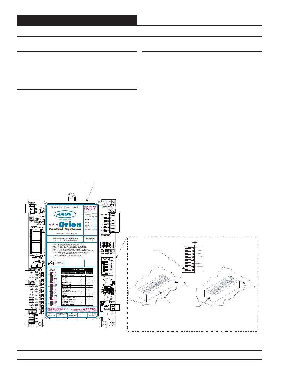
Figure 38: RNE Controller Address Switch Setting
RNE Controller
16
32
--------
NET
8
4
2
1
Address Switch Shown Is
Set For Address 1
Address Switch Shown Is
Set For Address 13
Controller
Address Switch
This Switch Should Be
In The OFF Position
As Shown
Note:
The Power To The Controller Must Be Removed And
Reconnected After Changing The Address Switch Settings In
Order For Any Changes To Take Effect.
Caution:
Disconnect All Communication Loop Wiring From The
Controller Before Removing Power From The Controller.
Reconnect Power And Then Reconnect Communication Loop
Wiring.
ADDRESS
ADD
ADD
ADD
The Address For Each Controller
Must Be Unique To The Other Controllers
On The Local Loop And Be Between 1 and 59