Installation and wiring, Rne modular controller field technical guide, Full digital module – Orion System RNE Modular Controller User Manual
Page 43
RNE Modular Controller Field Technical Guide
INSTALLATION AND WIRING
43
AO1
AO2
+5V
SIG 2
GND
OPTI
O
N
S
ALARM
ANALOG
STAT
+5V
COMM
GND
SIG 4
GND
BIN 2
R1
R2
GND
RELAYS
ADDRESS
SIG 3
+5V
GND
BIN 1
COM
+5V
SIG 1
R3
R4
Rc
AO1
AO2
PWM1-
PWM1+
PWM2-
PWM2+
OE370-23-FD-A
Full Digital Module
This Dip
Switch Is Not
Used For This
Application
This Dip
Switch Is Not
Used For This
Application
PWR
Connect To
RNE Controller
Connect To
Head Pressure Module(s)
HSSC Cable
24 VAC Transformer
3 VA Minimum
Line Voltage
24 V
A
C
GND
WARNING!!
Observe Polarity! All
boards must be wired
with GND-to-GND and
24 VAC-to-24 VAC.
Failure to observe
polarity could result in
damage to the boards.
HSSC Cable
NOTE:
NORMALLY OPEN AND
RATED FOR 24 VAC POWER
ALL RELAY OUTPUTS
ARE
COMPRESSOR 3 ENABLE
COMPRESSOR 1 ENABLE
R1
R4
R3
R2
COMPRESSOR 2 ENABLE
COMPRESSOR 4 ENABLE
ONLY.
1 AMP MAXIMUM LOAD.
HVAC UNIT CONNECTIONS
SIG 1
GND
+V
BK
RD
WH
OE275-01 Suction
Pressure Transducers 1 - 4
AO1
O
SIG 2
GND
+V
BK
RD
WH
SIG 3
GND
+V
BK
RD
WH
SIG 4
GND
+V
BK
RD
WH
Compressor 1
Compressor 2
COM
+
COM
+
Compressor 3
Compressor 4
COM
+
COM
+
GND
1
3
2
4
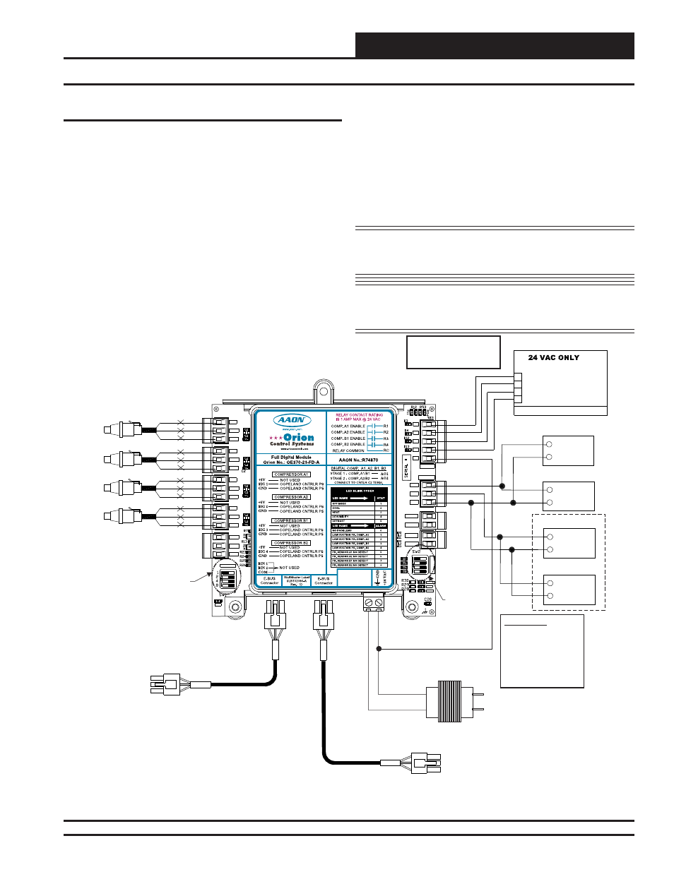
RNE 120 - 140 Ton Unit Compressor and Condenser Wiring
Figure 35: RNE 120 - 140 Ton Unit Four Compressor Full Digital Module Wiring
Full Digital Module
RNE Units with DX Cooling will have either a Half VFD/Half Fixed
compressor confi guration or a Full VFD compressor confi guration. The
RNE 120 - 140 Ton units have four compressors and will have either
two VFD and two Fixed Compressors or will have four VFD Compres-
sors. The operation of these compressors is described in the Sequence
of Operation section of this manual.
If this is not a Water Source Heat Pump unit, the outputs to the com-
pressors will always be wired from the Full Digital Module ( OE370-
23-FD-A). Each compressor will need to have a relay confi gured and
wired from this module, and the VFD output(s) will be wired from this
module. Each compressor will also have a Suction Pressure Transducer
wired into this module. See Figure 35 below for the wiring diagram.
On units confi gured for Half VFD/Half Fixed operation, the two VFD
Compressors will both be driven from Analog Output (AO) #1, although
the individual compressor relays will be enabled separately as needed.
On units confi gured for Full VFD operation, the 1st two VFD Compres-
sors will be driven from AO #1 and the 2nd two VFD Compressors
will be driven from AO #2, although all four compressor relays will be
enabled separately as needed.
The Full Digital Module connects to the RNE Controller or a Two
Condenser Head Pressure Module with an HSSC Cable. This allows
setpoints, status values, and alarms to be communicated between the
RNE Controller and the Full Digital Module. This module requires a
24 VAC power connection with an appropriate VA rating.
NOTE: The Compressor Relays on the Full Digital Module
are used rather than the relay outputs on the RNE
Controller.
NOTE: For more information, see the Full Digital Module
Technical Guide found on our website orioncontrols.
com.