Rne controller troubleshooting, Led diagnostics, Rne modular controller field technical guide – Orion System RNE Modular Controller User Manual
Page 71: Diagnostic led operation
RNE Modular Controller Field Technical Guide
RNE CONTROLLER TROUBLESHOOTING
71
LED Diagnostics
Diagnostic LED Operation
When power is fi rst applied, the STATUS 1 and STATUS 2 LEDs will be
off for 1 second. At this time, both LEDs will blink to indicate the setting
of the address switch and then will extinguish for 5 seconds. Verify that
the address switch setting is correct by counting the number of blinks.
If the address switch is not correct, fi rst remove the communication
loop terminal plug from the controller and then from the power terminal
plug. Set the address dip switches correctly. See Figure 38 on page 48
for correct address switch setting instructions. After you are sure the
address switch setting is correct, fi rst reconnect the power connection
and then reconnect the communication loop connection to the controller.
NOTE: You must always cycle power to the Controller being
addressed after changing address switch settings in order
for the changes to take effect.
Reapply power to the controller and observe the blink code to verify
the address is set correctly. If the STATUS 1 and STATUS 2 LEDs now
blink the correct address, your controller is addressed correctly. If they
don’t light up at all, the controller is not operating correctly and could
be defective. Once the controller is done blinking the address, STATUS
2 LED will blink continuously for 30 seconds while the controller
calibrates. Once the controller is done calibrating, the LEDs will blink
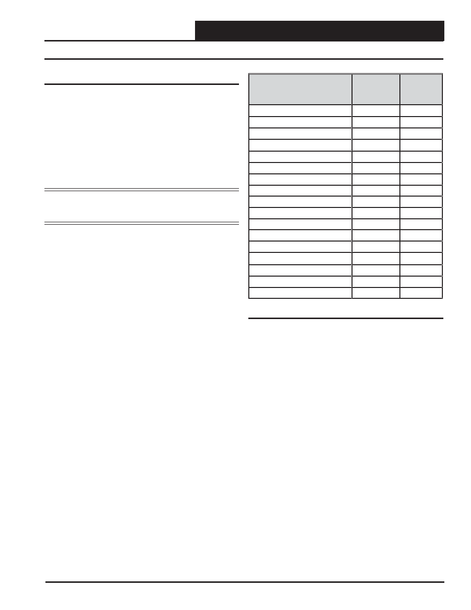
a code every 10 seconds to indicate controller status. See Table 3 for a
list of the various blink codes and their meanings.
If all of these tests are made and the controller still doesn’t operate,
please contact WattMaster Controls Technical Support at 866-918-1100.
Blink Code Description
STATUS 1
LED
Blinks
STATUS
2 LED
Blinks
Normal Operation
0
1
Outdoor Air Sensor Failure
0
2
Supply Air Sensor Failure
1
2
Space Sensor Failure
3
2
Module Alarm
4
2
Mechanical Cooling Failure
1
3
Mechanical Heating Failure
2
3
Fan Proving Failure
3
3
Dirty Filter Alarm
4
3
Emergency Shutdown
5
3
Low Supply Temp Alarm
1
4
High Supply Temp Alarm
2
4
Control Temp Cooling Failure
3
4
Control Temp Heating Failure
4
4
Push Button Override
1
5
Zone Override
2
5
Force Outputs Override
0
6
Table 3: Diagnostic LED Blink Code Interpretation