Installation and wiring, Rne modular controller field technical guide, Title 24 economizer actuator feedback – Orion System RNE Modular Controller User Manual
Page 33: Building pressure sensor
RNE Modular Controller Field Technical Guide
INSTALLATION AND WIRING
33
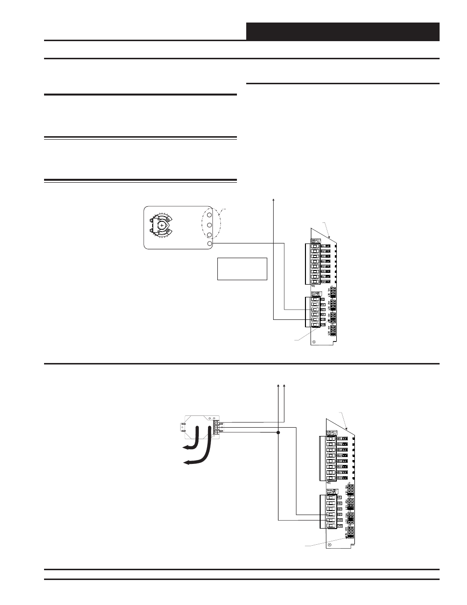
Title 24 Economizer Actuator Feedback & Building Pressure Sensor
Title 24 Economizer Actuator
Feedback
If the controller has been confi gured for Title 24 Economizer operation,
the Economizer Actuator Feedback signal is wired to the AI3 input on
the VCM-X Expansion Module. It must be wired as shown in Figure
24 below for proper controller operation.
Warning: It is very important to be certain that all wiring is cor-
rect as shown in the wiring diagram below. Failure to observe the
correct polarity will result in damage to the HVAC Unit Controller
and the VCM-X Expansion Module.
Figure 24: Title 24 Economizer Actuator Feedback Wiring
AI3
GND
To GND
Jumper Must
Be Set To
0-10V As Shown
VCM-X Expansion
Module
Title 24 Economizer
Actuator Feedback
Signal 0-10VDC
(By Others)
Economizer Damper Actuator
(Belimo Actuator Shown)
Y1 3
+ 2
COM - 1
Economizer Feedback 5
Belimo Actuator Wiring
Shown. Consult Factory
For Other Manufacturer
Wiring Instructions
NOTE: For Economizer
Actuator Wiring, See
Wiring For The
RNE Controller.
AO1
See Economizer
Actuator Wiring
For RNE
Controller
AO1
Building Pressure Sensor
The OE258-01 Building Pressure Sensor must be wired as shown in the
illustration below for proper operation. There are 3 terminal connections
on the Building Pressure Sensor. Connect the power side of the 24 VAC
power source to the terminal labeled “+ EXC.” Connect the GND side
of the 24 VAC power source to the terminal labeled “- COM.” Connect
the remaining terminal labeled “OUT” to AI4 on the VCM-X Expansion
Module terminal block. See Figure 25 below for detailed wiring. The
AI4 Jumper on the expansion module must be set for 0-5VDC operation
for the Building Pressure Sensor to operate correctly.
AI4
GND
Jumper Must
Be Set To
0-5V As Shown
EXC
COM
OUT
LOW
-
+
+
+
Tubing To Building
Pressure Sensing Location
Tubing To Atmospheric
Pressure Sensing Location
-
+
Building Pressure Sensor
HIGH
VCM-X Expansion
Module
To
GND
24
VAC
Figure 25: OE258-01 — Building Pressure Sensor Wiring