Verilink QPRI 2921 (880-503143-001) Product Manual User Manual
Page 20
Quick Set-Up
2-4
Verilink QPRI 2921
Reconnect to the NCM Local port for further operations.
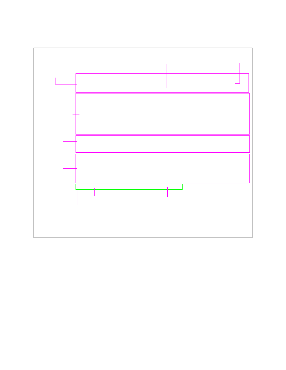
Figure 2-2 NCM Main Menu
-- VERILINK NCM CONTROLLER : FW Rev 4.15, Dec 13 1997 12:53:30 --
-- VERILINK NCM CONTROLLER : FW Rev 4.15, Dec 13 1997 12:53:30 --
-- VERILINK NCM CONTROLLER : FW Rev 4.15, Dec 13 1997 12:53:30 --
-- VERILINK NCM CONTROLLER : FW Rev 4.15, Dec 13 1997 12:53:30 --
Site Name: Verilink Test Access Level: 2
Site Name: Verilink Test Access Level: 2
Site Name: Verilink Test Access Level: 2
Site Name: Verilink Test Access Level: 2
Managing at NEAR end node [127.255.255.0] Node ID: 0
Managing at NEAR end node [127.255.255.0] Node ID: 0
Managing at NEAR end node [127.255.255.0] Node ID: 0
Managing at NEAR end node [127.255.255.0] Node ID: 0
<- SLOT ->
<- SLOT ->
<- SLOT ->
<- SLOT ->
SHELF 1 2 3 4 5 6 7 8 9 10 11 12 13
SHELF 1 2 3 4 5 6 7 8 9 10 11 12 13
SHELF 1 2 3 4 5 6 7 8 9 10 11 12 13
SHELF 1 2 3 4 5 6 7 8 9 10 11 12 13
0 - - - - - - - - - - - - -
0 - - - - - - - - - - - - -
0 - - - - - - - - - - - - -
0 - - - - - - - - - - - - -
1 D *N [X]
1 D *N [X]
1 D *N [X]
1 D *N [X]
2 - - - - - - - - - - - - -
2 - - - - - - - - - - - - -
2 - - - - - - - - - - - - -
2 - - - - - - - - - - - - -
3 - - - - - - - - - - - - -
3 - - - - - - - - - - - - -
3 - - - - - - - - - - - - -
3 - - - - - - - - - - - - -
4 - - - - - - - - - - - - -
4 - - - - - - - - - - - - -
4 - - - - - - - - - - - - -
4 - - - - - - - - - - - - -
KEY: A=DIDCSU, B=DIU/DBU, C=CSU, D=DIU, E=SDIU, F=DIU/DDS, G=DHDM,
KEY: A=DIDCSU, B=DIU/DBU, C=CSU, D=DIU, E=SDIU, F=DIU/DDS, G=DHDM,
KEY: A=DIDCSU, B=DIU/DBU, C=CSU, D=DIU, E=SDIU, F=DIU/DDS, G=DHDM,
KEY: A=DIDCSU, B=DIU/DBU, C=CSU, D=DIU, E=SDIU, F=DIU/DDS, G=DHDM,
H=ATM/IMUX, I=IDCSU, J=PEP, K=DAC, L=HLM, M=IMUX, N=NCM, P=QPRI,
H=ATM/IMUX, I=IDCSU, J=PEP, K=DAC, L=HLM, M=IMUX, N=NCM, P=QPRI,
H=ATM/IMUX, I=IDCSU, J=PEP, K=DAC, L=HLM, M=IMUX, N=NCM, P=QPRI,
H=ATM/IMUX, I=IDCSU, J=PEP, K=DAC, L=HLM, M=IMUX, N=NCM, P=QPRI,
Q=QUAD, R=SUBRATE, S=HSM, T=HDM, U=DCSU, V=VCU, X=QPRI
Q=QUAD, R=SUBRATE, S=HSM, T=HDM, U=DCSU, V=VCU, X=QPRI
Q=QUAD, R=SUBRATE, S=HSM, T=HDM, U=DCSU, V=VCU, X=QPRI
Q=QUAD, R=SUBRATE, S=HSM, T=HDM, U=DCSU, V=VCU, X=QPRI
S) shelf/slot O) administration
S) shelf/slot O) administration
S) shelf/slot O) administration
S) shelf/slot O) administration
C) configuration D) diagnostics
C) configuration D) diagnostics
C) configuration D) diagnostics
C) configuration D) diagnostics
P) performance/status A) alarm
P) performance/status A) alarm
P) performance/status A) alarm
P) performance/status A) alarm
B) circuit manager I) manufacturing info
B) circuit manager I) manufacturing info
B) circuit manager I) manufacturing info
B) circuit manager I) manufacturing info
X) exit this screen
X) exit this screen
X) exit this screen
X) exit this screen
A [127.255.255.0] [1,1] QPRI >
A [127.255.255.0] [1,1] QPRI >
A [127.255.255.0] [1,1] QPRI >
A [127.255.255.0] [1,1] QPRI >
Menu Heading Area
Node “Map” (Physical
Location of Modules)
Command List
Firmware Version and Date of Release
Access Level (1-4)
Node Address
Node Address
Data (Command) Entry Area
Module Key
Active NCM Master Designator
❷
❸
❶
❷
❸
❶
Asterisk indicates that the NCM is the Main Controller in the shelf
Indicator for the type of shelf: M= Multi-line, D = Dual-line
Brackets around module letter ( [X] ) indicate current module selected