Unit screen, Unit screen -2 – Verilink WANsuite 5330 (34-00302.F) Product Manual User Manual
Page 30
3-2
W A N s u i t e 5 3 3 0
displays the hardware and software revision and serial numbers under which
the unit is operating.
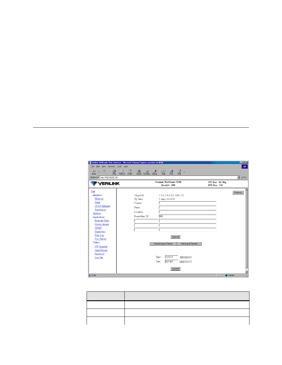
The area beneath the upper frame is divided into two side-by-side frames. The
frame on the left side of this area depicts a hierarchical “tree” structure used
to navigate through the various interface screens. Each “branch” on the tree
guides you to more specific upper-level information about the unit and its
configuration. Note that the Applications and Utilities branches do not link to
an actual displayed page
−
these branches are simply used to provide structure
for navigation. The frame on the right side of the screen will display all the
configuration screens. The Unit screen represents the top of the navigation
tree. The screen captures throughout this chapter show only the configuration
portion of the screen, except in the case of the Unit screen, which shows all
three frames. The Unit screen represents the top of the navigation tree.
Unit Screen
The first screen displayed by the unit’s Web server interface is the Unit
screen (Figure 3.1). It lets you view and set specific information about the
unit in service.
Figure 3.1
Web Server Interface, Unit Screen
The Unit screen displays the following fields:
Field
Function
Object ID
Display-only field used to point an SNMP agent to this ID.
Up Time
Displays the amount of time the unit has been up and running.
Contact
Stores the name of a point-of-contact for system failure.