Error status and alarm thresholds table, Error status and alarm thresholds table -7 – Verilink WANsuite 5330 (34-00302.F) Product Manual User Manual
Page 85
V T 1 0 0 I n t e r f a c e
4-7
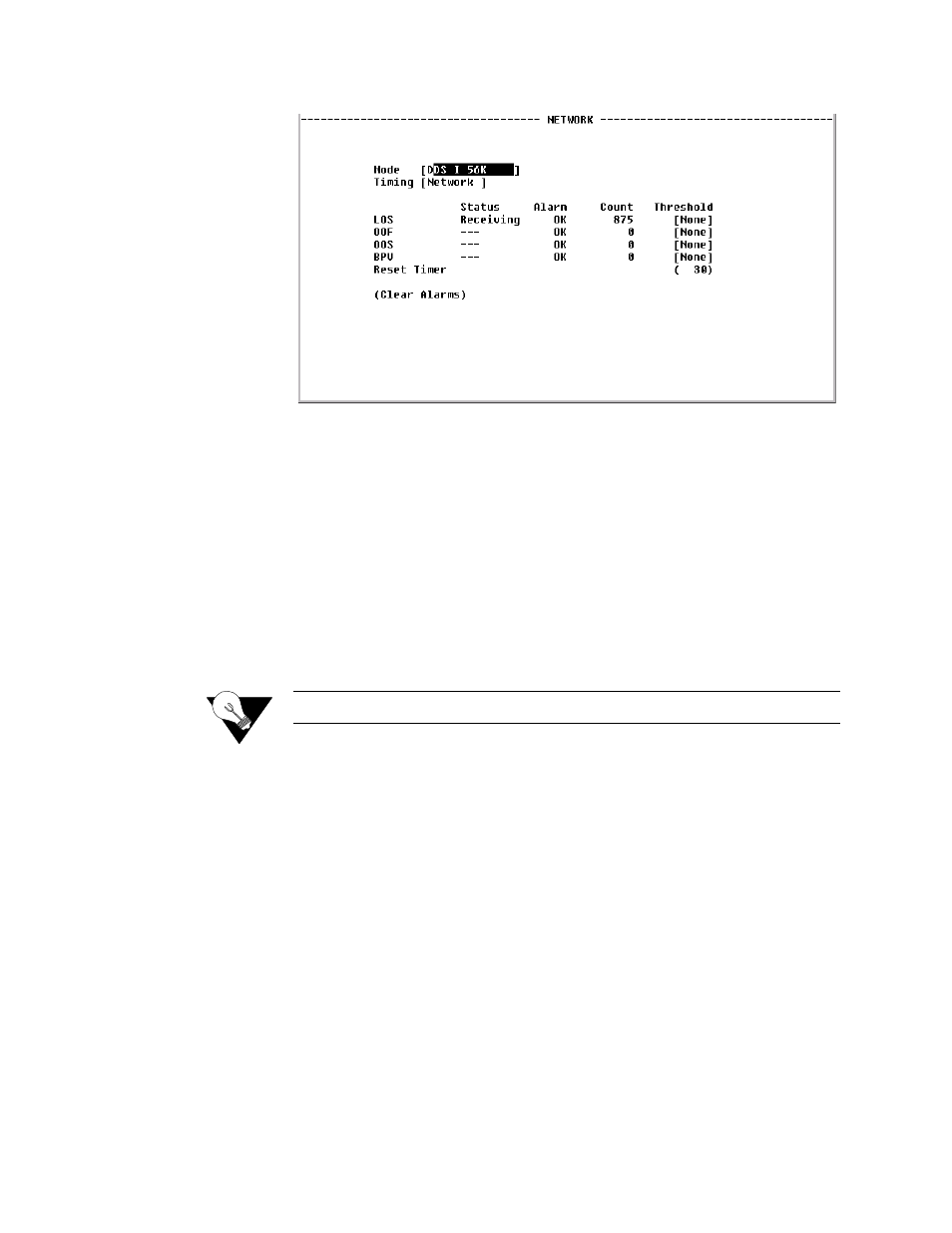
Figure 4.7
Network Screen
Mode
Selects the network service type.
Values
DDS I 56K, DDS II CC-64K
Default: DDS I 56K
Timing
Sets the timing source to synchronize the unit’s internal timing generators.
Choices are as follows:
Internal – The unit’s internal frequency standard is used for all timing.
Network – Timing is derived from the network recovered clock. (Most
applications use this selection.)
Values: Network, Internal
Default: Network
NOTICE:
Internal timing is valid only in 56K mode.
Error Status and Alarm Thresholds Table
The unit can be programmed to generate an alarm condition based on a
specific level of performance degradation. The Network screen presents a
table that provides current error status, alarm condition, error count, and alarm
threshold information.
Acceptable alarm thresholds are set for periods of 1
−
5, 10, 20, or 30 seconds
(900 seconds) sampled every second. The types of error conditions listed in
the following paragraphs can be preset to a value selected from the available
enumeration list of thresholds (displayed as a pull-down menu). Setting a
threshold field to “None” disables the alarm for that condition. To effectively
disable alarm reporting, set all fields to “None.”
The 15-minute time frame is a time window based on the accumulated counts
over the previous 15 one-minute intervals. In all cases, if the number of actual
network errored seconds in the previous 15 minutes reaches the preset
threshold for the specified error type, an alarm condition is declared.