Installation, 8900net module alarm dip switches – Grass Valley 8900NET v.4.4.0 User Manual
Page 11
8900NET (Net Card) — Instruction Manual
11
Installation
Installation
This section describes placing the module in Gecko 8900 and GeckoFlex
frames and cabling the communications ports for all frame types. Proce-
dures for DIP switch settings, installation, and cabling of the module are
described in this section.
An 8900NET module will come installed in Gecko 8900TF/TFN and
GeckoFlex 8900FF/FFN frames. Note that there are two DIP switches
described below that will affect reporting to the 8900NET module, the
external RS-232 Frame Alarm, and the SNMP reporting system.
Note
The GeckoFlex frame requires an 8900NET module running 4.0.0 or later
software. See
8900NET Software to Part Number Guide on page 66
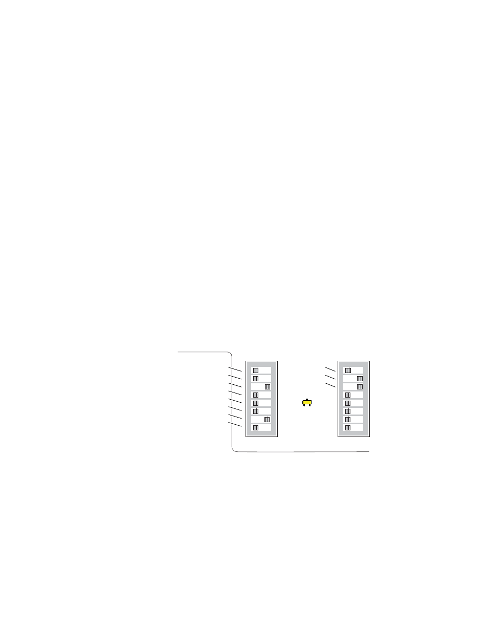
8900NET Module Alarm DIP Switches
There are two eight-position DIP switches (S1 and S2) on the 8900NET
module for enabling or disabling the overall status reporting of the frame
and modules.
illustrates the DIP switches set with the factory
gives the function of each DIP switch set-
ting. You may enable or disable reporting functions from this point.
Note
Some web page and frame alarm and SNMP reporting functions must be
enabled on the DIP switches to be functional.
Figure 3. Alarm Reporting DIP Switches (Defaults Shown)
The current status of the DIP switch settings is always reported on the
8900NET Status (
), LED
Reporting (
), and SNMP Reporting (
) frame web pages. You
may check DIP switch status on these web pages instead of pulling out the
module.
Refer to
for the location of S1 and S2 on the 8900NET
module and
for the possible settings. A settings table is
also silk-screened on the bottom of the module. Disabling (or filtering) of
fault reports can sometimes be useful in isolating problems in the frame.
12345678
12345678
S2
S1
Power Supply #1
Power Supply #2
Temperature (not used)
Fan
Module
Frame Bus
Fan Speed
NM Control
Status
8900NET
IP Address
Frame Control
Remote
Override
LED
0612_28
r2