3 explanation of symbols, 1 symbols on the inverter – SMA STP 10000TL-10 Installation User Manual
Page 11
SMA Solar Technology AG
2 Safety
Installation Manual
STP10-17TL-IA-en-32
11
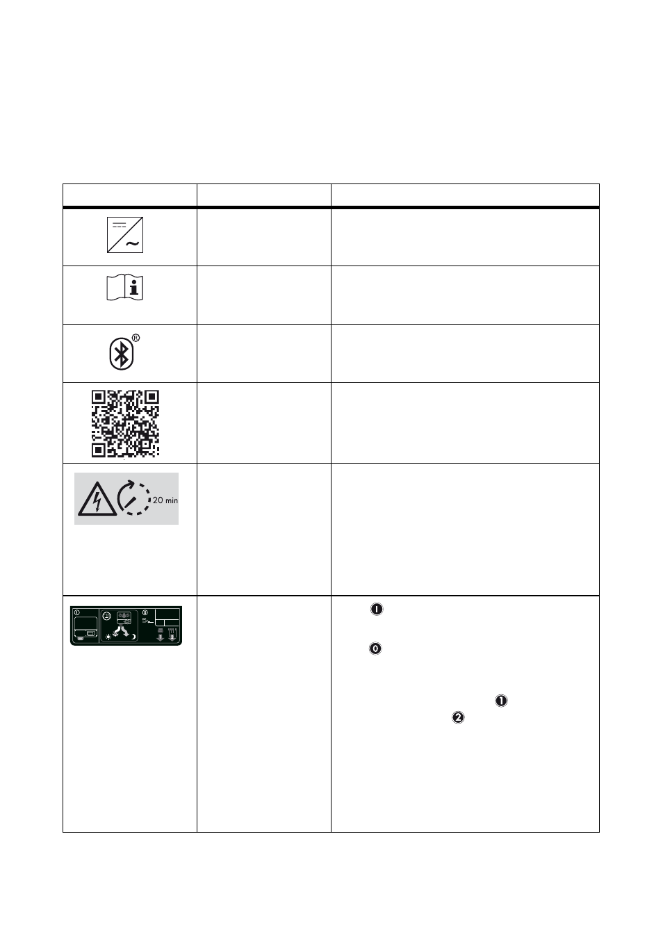
2.3 Explanation of Symbols
This section gives an explanation of all the symbols found on the inverter and on the type label.
2.3.1 Symbols on the Inverter
Symbol
Description
Explanation
Inverter
This symbol defines the function of the green LED.
The green LED indicates the operating state of
the inverter.
Observe the
documentation
This symbol defines the function of the red LED
which indicates a fault or disturbance. Read the
manual to remedy the fault or disturbance.
Bluetooth
This symbol defines the function of the blue LED.
The blue LED indicates that communication via
Bluetooth is activated.
QR Code
®
Links to additional information on the inverter can
be found at www.SMA-Solar.com.
Danger to life due to
high voltages in the
inverter
The capacitors in the inverter may be charged
with very high voltages.
• Disconnect the inverter from all voltage
sources (see Section 9) and wait
20 minutes before opening the upper
enclosure lid in order to allow the
capacitors to discharge.
Stickers on the ESS
•
When the Electronic Solar Switch is
plugged in, the DC circuit is closed.
•
To interrupt the DC circuit and
safely disconnect the inverter when under
load, you must first remove the
Electronic Solar Switch and then all
DC connectors (see Section 9
"Disconnecting the Inverter from Voltage
Sources", page 61). Only unplug the
Electronic Solar Switch if the inverter is not
displaying any error message prohibiting
the removal of the ESS and the inverter is
not beeping.