System configuration, Rs-422, Rs-232c – Yaskawa MP940 Hardware Manual User Manual
Page 25: Rs-232c display panel
MotionSuite™ MP940 Machine Controller Hardware Manual
Section 5: Communications
22
System Configuration
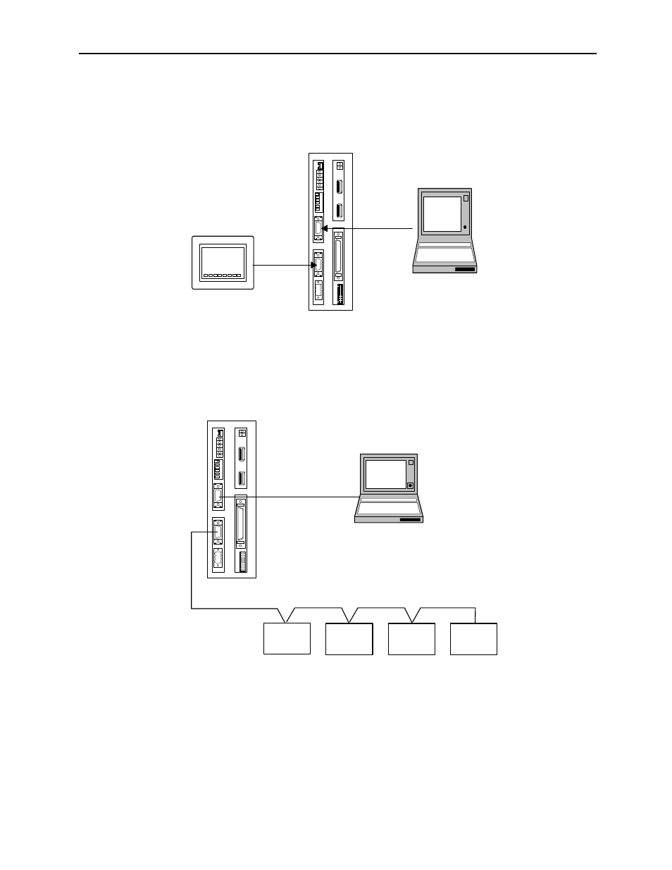
The figure below illustrates connection of a PC and an operator interface to the
MP940.
The figure below illustrates connection of a MotionSuite™ programming tool to the
RS-232C port and branched connection of peripheral devices from the RS-485 port.
Figure 5.2: Serial System Configuration
BAT
RDY
RUN
ALM
BAT
PRT1
6
5
4
3
2
1
NO
¨
PRT2
RUN
INIT
TEST
FLASH
PP
COPY
PORT1
PORT2
POWER
+24V
GND
FG
LED
I/O
TX
R
X
1
2
M
E
C
H
A
T
R
O
L
I
N
K
MP940
RS-232C
Display
Panel
RS-422
Figure 5.3: Branched Connection of Peripheral Devices
BAT
RDY
RUN
ALM
BAT
PRT1
6
5
4
3
2
1
NO
→
PRT2
RUN
INIT
TEST
FLASH
PP
COPY
PORT1
PORT2
POWER
+24V
GND
FG
LED
I/O
TX
R
X
1
2
M
E
C
H
A
T
R
O
L
I
N
K
MP940
External
Device
External
Device
External
Device
External
Device
RS-485
Notebook PC
RS-232C