Mechatrolink connection, Figure 5.8: terminal connectors, I/o350 – Yaskawa MP940 Hardware Manual User Manual
Page 31
MotionSuite™ MP940 Machine Controller Hardware Manual
Section 5: Communications
28
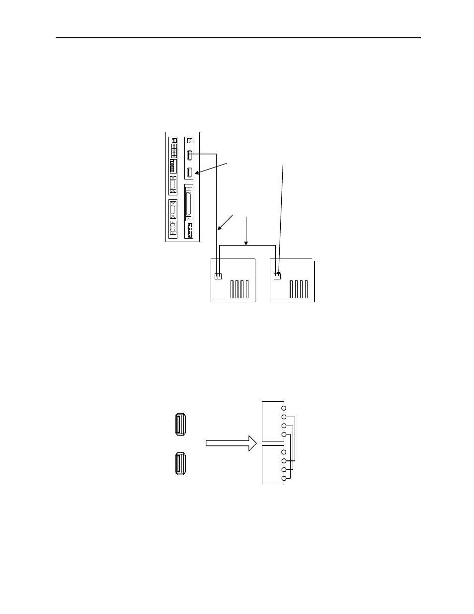
Mechatrolink Connection
The following figure shows the connection of the MP940 module to an I/O350 unit.
Use the standard cable (JEPMC-W6000-A3) when connecting an MP940 module to
an I/O350, or when connecting one I/O350 to another I/O350.
Insert the USB terminator (JEPMC-W6020) into the terminal connector ((1) or (2) in
the figure below). The mechatrolink connectors 1 and 2 are the same; the terminator
may be inserted into either one.
Insert a USB terminator (JEPMC-W6020) into unused ports.
There is only one channel per Mechatrolink port in the MP940 module. As shown in
the figure above, the top and bottom of the connector are the same although there are
two receptacles.
BAT
RDY
RUN
ALM
BAT
PRT1
6
5
4
3
2
1
NO
¨
PRT2
RUN
INIT
TEST
FLASH
PP
COPY
PORT1
PORT2
POWER
+24V
GND
FG
LED
I/O
TX
R
X
1
2
M
E
C
H
A
T
R
O
L
I
N
K
MP940
I/O350
I/O350
JEPMC-W6000-A3
USB Terminator JEPMC-W6020
Figure 5.7: MP940 Connection to Multiple I/O 350 Modules
1
2
ME
CHA
T
R
OLINK
SRD-
(
NC)
SRD+
SH
SRD-
(
NC)
SRD+
SH
Figure 5.8: Terminal Connectors
NC
SRD-
SRD+
SH
NC
SRD-
SRD+
SH