I/o circuit of i/o connector – Yaskawa MP940 Hardware Manual User Manual
Page 69
Advertising
MotionSuite™ MP940 Machine Controller Hardware Manual
Section 13: Dimensional Drawings and Cable Diagrams
66
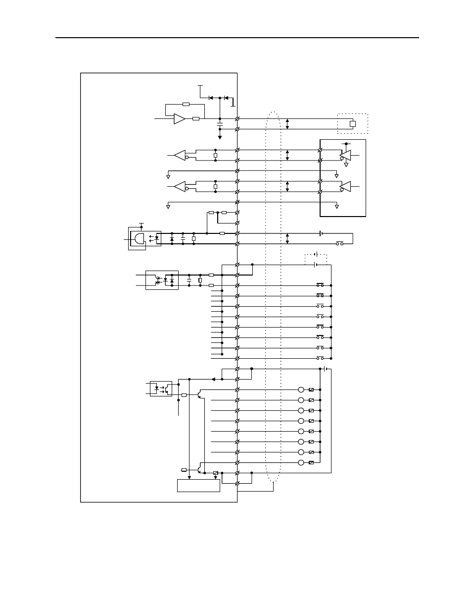
I/O Circuit of I/O Connector
47
Ω
1k
Ω
-
+
+15V
-15V
390
Ω
+5V
0V
P
A-phase
1
26
L
-10~+10V
4
390
Ω
P
6
External Encoder
31
10
9
35
34
680
Ω
+5V
P
38
14
13
39
15
16
41
40
17
42
45
21
20
46
22
23
48
47
24
49
25
50
Fuse
Fuse Detection
Circuit
Fuse
L
L
L
L
L
L
L
L
Analog
Output
Latch Input
Digital Input
Digital Output
External Device
Latch Input
Exte
rn
al In
pu
t Si
gn
al
E
xte
rn
al O
utput
Si
gnal
P
5
B-phase
29
30
External Encoder
AG
0V
Digital Ground
Digital Ground
Shield
0V
Input 1
Input 2
Input 3
Input 4
Input 5
Input 6
Input 7
Input 8
Output 1
Output 2
Output 3
Output 4
Output 7
Output 6
Output 5
Output 8
Shell*
N ote: S ee Figure 3 for shield to connector shell term ination details
Advertising