6 procedure a – Yaskawa V1000-Series Option SI-EP3/V PROFINET User Manual
Page 24
6 Procedure A
24
YASKAWA TOEP YEACOM 06A V1000 Option PROFINET SI-EP3/V Installation Manual
4.
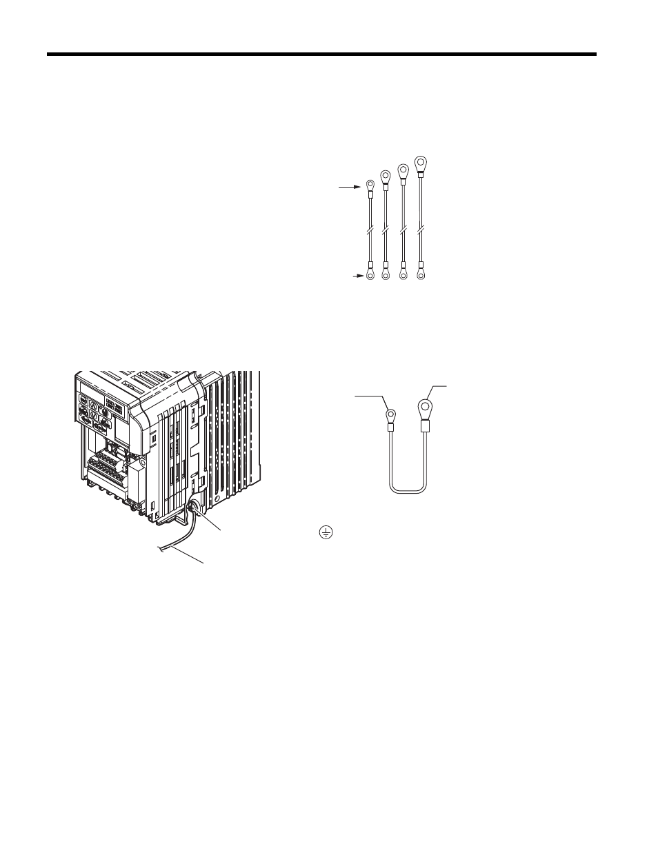
Select one of the four different length ground wires packaged with the option.
Choose the proper ground wire by first removing the ground terminal screw from the
drive,
. Test fit the screw (size M3.5 to M6) into each of the four ground
drive-side ring lugs prior to installation. Ground wire selection varies by drive model.
Figure 10
Figure 10 Ground Wire Selection
5.
On IP20/Open-Chassis models, connect the drive side of the ground wire to the
drive ground terminal.
Figure 11
Figure 11 Ground Wire Connection on IP20/Open-Chassis
6.
Proceed to STEP
on page
to continue the option installation procedure for
IP20/Open-Chassis models.
To Option ground screw FE
Screw size: M3
To drive ground terminal
Screw size: M3.5 to M6
Ground terminal
Ground wire
Ground wire
Drive-side
ground terminal
ring lug (size varies):
M3.5 to M6
Ring lug for
Option ground FE
Size: M3