7 procedure b – Yaskawa V1000-Series Option SI-EP3/V PROFINET User Manual
Page 40
7 Procedure B
40
YASKAWA TOEP YEACOM 06A V1000 Option PROFINET SI-EP3/V Installation Manual
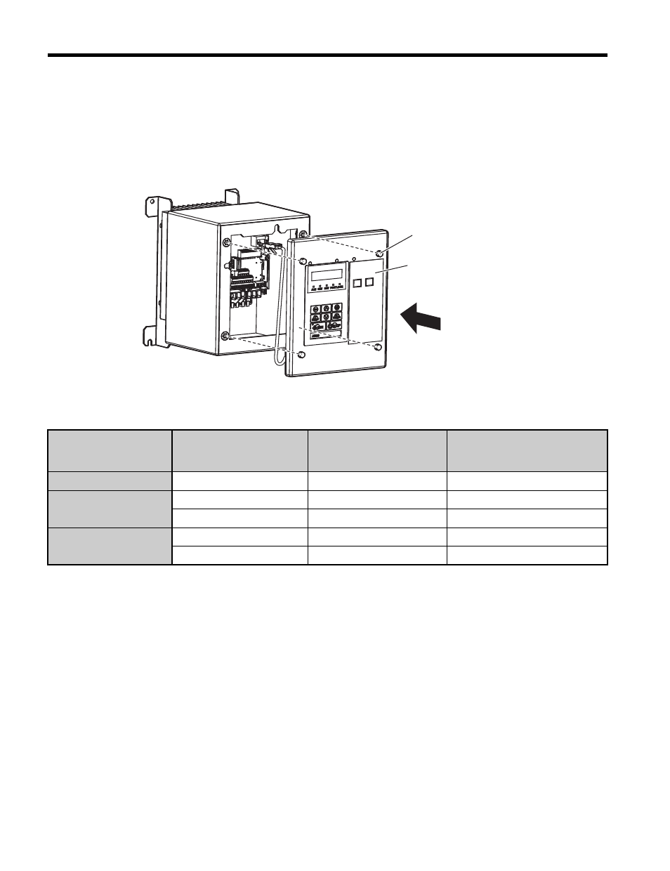
14.
Reattach the front cover of the drive using four bolts,
. Refer to
on
page
for tightening torque specifications.
NOTICE: Damage to Equipment. Take proper precautions when wiring the option so that the front covers
will easily fit back onto the drive. Make sure no cables are pinched between the front covers and the drive
when replacing the cover. Failure to comply may result in damage to circuitry and equipment.
Figure 38
Figure 38 Attach Cover to Drive
Table 9 Front Cover Installation Bolt Size and Tightening Torque
15.
Set drive parameters in
for proper option performance.
16.
End of Procedure B.
Voltage Class
Model No. CIMR-V
Installation
Screw Size
Tightening Torque
Nm
(lb-in)
Single Phase 200 V Class
BA0001 to BA0012
M5
2.0 to 2.5 (17.7 to 22.1)
Three Phase 200 V Class
2A0001 to 2A0020
M5
2.0 to 2.5 (17.7 to 22.1)
2A0030 to 2A0069
M6
5.4 to 6.0 (47.8 to 53)
Three Phase 400 V Class
4A0001 to 4A0011
M5
2.0 to 2.5 (17.7 to 22.1)
4A0018 to 4A0038
M6
5.4 to 6.0 (47.8 to 53)
Front cover
Front cover screw
Drive