Installation procedure – Yaskawa GPD 515-G5 Modbus RTU User Manual
Page 11
3-2 Installation of CM086 Board
Installation Procedure
These procedures should be followed when installing the CM085 board into the GPD 515 drive.
1.
Turn the main power OFF to the drive. Remove the front cover of the drive to verify that the
CHARGE lamp is off.
2.
Position the CM085 board onto the control board of the drive, lining up the 2CN connector on
the CM085 board with the 2CN connector on the control board of the drive.
3.
Position the two spacer holes on the right side of the CM085 board with the plastic stand-offs
on the control board. Snap the CM085 board onto the stand-offs tightly.
4.
Plug the 6CN cable from the CM085 board into location 6CN on the control board.
5.
Connect the green wire (labeled ëEí) from the CM085 board to terminal 12 on the drive.
6.
After installing the CM085 board onto the drive, connect with peripheral devices and replace
the cover of the drive.
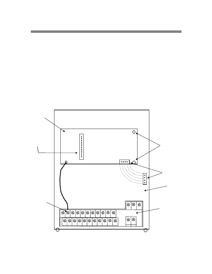
Figure 3-1. Position of the CM085 Board on the GPD 515 Drive
Drive Control
Board
2CN
Connector
CM085
Board
Spacer Holes
inserted onto
stand-offs
Ground
Terminal
Main Control
Terminals
Terminal Block
E
6CN
Connection