Yaskawa GPD 515-G5 Modbus RTU User Manual
Page 57
7-21
Registers
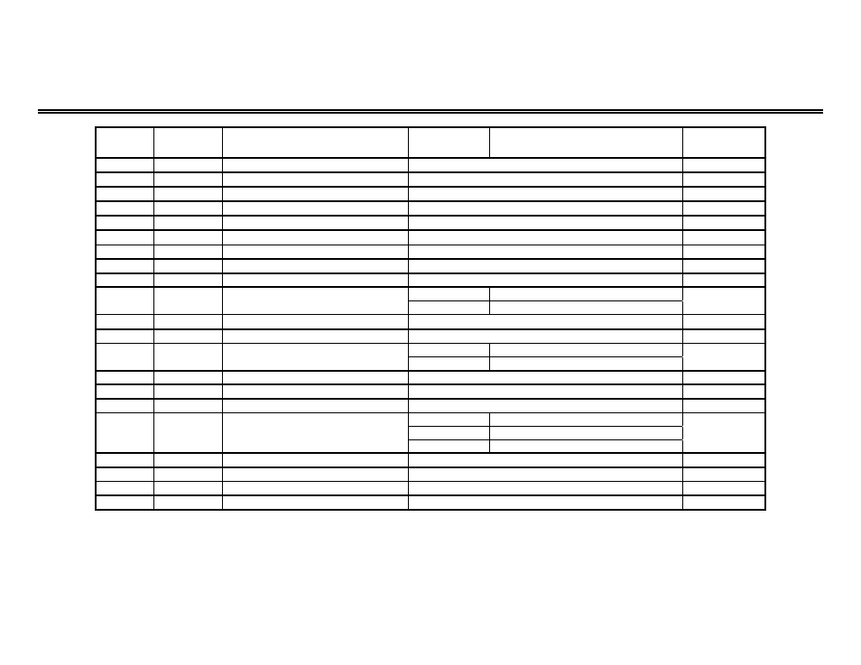
Drive Parameter Registers (Read/Write) (continued)
REGISTER PARAMETER
PARAMETER
PARAMETER
LIMITS / DESCRIPTION
INITIAL
(in hex)
FUNCTION
SETTING
VALUE
400h
H1-01
Multi-function Input (terminal 3)
0 to 77h
24h
401h
H1-02
Multi-function Input (terminal 4)
0 to 77h
14h
402h
H1-03
Multi-function Input (terminal 5)
0 to 77h
3 (or 0) (1)
403h
H1-04
Multi-function Input (terminal 6)
0 to 77h
4 (or 3) (1)
404h
H1-05
Multi-function Input (terminal 7)
0 to 77h
6 (or 4) (1)
405h
H1-06
Multi-function Input (terminal 8)
0 to 77h
8 (or 6) (1)
406h
H2-01
Multi-function Output (term. 9 & 10)
0 to 37h
0
407h
H2-02
Multi-function Output (term. 25-27)
0 to 37h
1
408h
H2-03
Multi-function Output (term. 26-27)
0 to 37h
2
409h
H3-01
Auto Speed Reference Signal
0
0 to 10 V DC
0
Level Selection (term. 13)
1
-10 to +10 V DC
40Ah
H3-02
Auto Speed Reference Signal Gain
0.0 to 1000.0%
100.0
40Bh
H3-03
Auto Speed Reference Signal Bias
-100.0 to +100.0%
0.0
40Ch
H3-04
Multi-function Analog Input 1 Signal
0
0 to 10 V DC
0
Level Selection (term. 16)
1
-10 to +10 V DC
40Dh
H3-05
Multi-function Analog Input 1 Select.
0 to 1Fh
0
40Eh
H3-06
Multi-function Analog Input 1 Gain
0.0 to 1000.0%
100.0
40Fh
H3-07
Multi-function Analog Input 1 Bias
-100.0 to +100.0%
0.0
410h
H3-08
Multi-function Analog Input 2 Signal
0
0 to 10 V DC
Level Selection (term. 14)
1
-10 to +10 V DC
2
2
4 to 20 mA
411h
H3-09
Multi-function Analog Input 2 Select.
0 to 1Fh
1Fh
412h
H3-10
Multi-function Analog Input 2 Gain
0.0 to 1000.0%
100.0
413h
H3-11
Multi-function Analog Input 2 Bias
-100.0 to +100.0%
0.0
414h
H3-12
Analog Input Filter Time Constant
0.00 to 2.00 seconds
0.00
Notes:
1. Initial value in the parentheses are values obtained at a 3-wire initialization.