3 i/o signal connections, 1 i/o signal (cn1) names and functions, 1) input signals – Yaskawa Sigma-5 Large Capacity Users Manual: Design and Maintenance-Rotary Motors-Mechatrolink-III Communication Reference User Manual
Page 69: 2) output signals
3.3 I/O Signal Connections
3-23
3
Wi
ring and
C
onne
ctio
n
3.3 I/O Signal Connections
This section describes the names and functions of I/O signals (CN1). Also connection examples by control
method are shown.
3.3.1 I/O Signal (CN1) Names and Functions
The following table shows the names and functions of I/O signals (CN1).
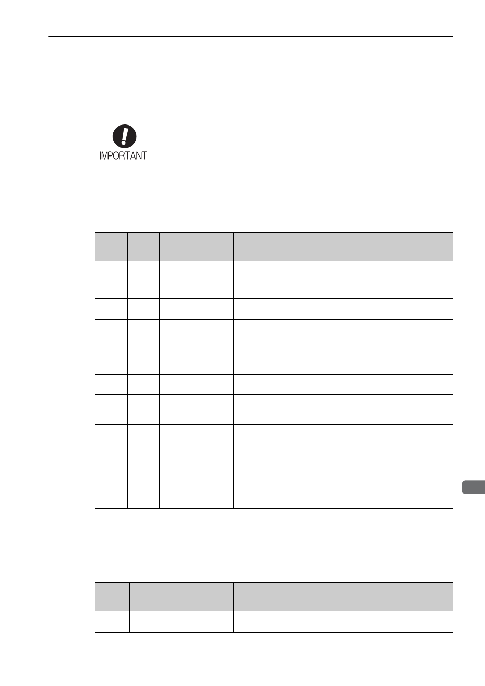
(1) Input Signals
Note 1. The allocation of the input signals (/SI0 to /SI6) can be changed. For details, refer to 3.4.1 Input Signal Alloca-
tions.
2. If the Forward run prohibited/ Reverse run prohibited function is used, the SERVOPACK or converter is stopped
by software controls, not by electrical or mechanical means. If the application does not satisfy the safety require-
ments, add an external circuit for safety reasons as required.
(2) Output Signals
The number of pins on the CN1 connector is different on a large-capacity
Σ-V SERVO-
PACK (50 pins) and a standard
Σ-V SERVOPACK (26 pins). If you are using both types
of SERVOPACK, use the correct connector model numbers when ordering and the cor-
rect signal assignments.
Signal Pin No.
Name
Function
Refer-
ence
Section
P-OT
(/SI2)
N-OT
(/SI3)
42
43
Forward run
prohibited,
Reverse run
prohibited
With overtravel prevention: Stops servomotor when movable
part travels beyond the allowable range of motion.
4.3.1
/DEC
(/SI1)
41
Homing deceleration
switch signal
Connects the deceleration limit switch for homing.
−
/EXT 1
(/SI4)
/EXT 2
(/SI5)
/EXT 3
(/SI6)
44
45
46
External latch signal 1
External latch signal 2
External latch signal 3
Connects the external signals that latch the current feedback
pulse counter.
−
/SI0
40
General-purpose input
signal
Used for general-purpose input.
Monitored in the I/O monitor field of MECHATROLINK.
−
+24VIN 47
Control power supply
for sequence signal
Control power supply input for sequence signals.
Allowable voltage fluctuation range: 11 to 25 V
Note: The 24 VDC power supply is not included.
3.5.1
BAT (+)
BAT (-)
21
22
Battery (
+) input signal
Battery (
−) input signal
Connecting pin for the absolute encoder backup battery.
Do not connect when the encoder cable with the battery case
is used.
3.7.2
4.7.1
/P-CL
/N-CL
/DBANS
Can be
allocated
Forward external
torque limit
Reverse external
torque limit
Dynamic brake answer
signal
The allocation of an input signal to a pin can be changed in
accordance with the function required.
−
Signal
Pin No.
Name
Function
Refer-
ence
Section
ALM+
ALM-
31
32
Servo alarm output
signal
Turns OFF when an error is detected.
−