1 mechatrolink-iii communications settings, 1 setting switches s1, s2, and s3, 1) settings of the rotary switches s1 and s2 – Yaskawa Sigma-5 Large Capacity Users Manual: Design and Maintenance-Rotary Motors-Mechatrolink-III Communication Reference User Manual
Page 99: M-iii, Ope rat ion
Advertising
4.1 MECHATROLINK-III Communications Settings
4-3
4
Ope
rat
ion
4.1 MECHATROLINK-III Communications Settings
This section describes the switch settings necessary for MECHATROLINK-III communications.
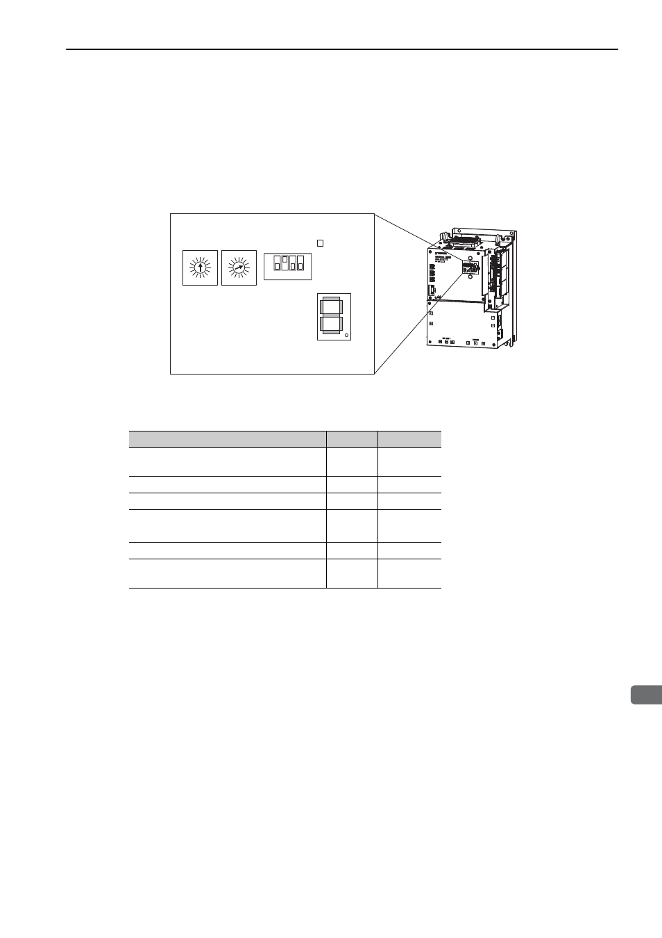
4.1.1 Setting Switches S1, S2, and S3
The DIP switch S3 is used to make the settings for MECHATROLINK-III communications.
The station address is set using the rotary switches S1 and S2.
(1) Settings of the Rotary Switches S1 and S2
Set the station address using the rotary switches S1 and S2.
ᴾ
4
3
5
2
6
1
7
C
8
0
F
9
E
A
D
B
4
3
5
2
6
1
7
C
8
0
F
9
E
A
D
B
ON
OFF
1
2
3
4
S3
Seven-segment
LED display
POWER LED
S2
S1
M-III
Station Address
S1
S2
00H to 02H: Disabled
(Do not use these addresses.)
0
0 to 2
03H (Factory setting)
0
3
04H
0
4
EFH
E
F
F0H to FFH: Disabled
(Do not use these addresses.)
F
0 to F
Advertising