Connections – Precision Digital PD941 User Manual
Page 14
ConsoliDator Multi-Channel Controller
Instruction Manual
14
Connections
Connections are made to removable screw terminal connectors and a DB9 male serial
connector. They are located around the sides of the controller.
!
Use copper wire with 60°C or 60/75°C insulation for all
line voltage connections. Observe all safety regulations.
Electrical wiring should be performed in accordance with
all applicable national, state, and local codes to prevent
damage to the instrument and ensure personnel safety.
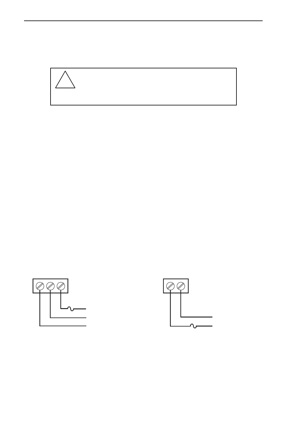
Power Connections
Power connections are made to one of the power terminal connectors. All units are capable
of being powered either by AC or by DC for the ranges specified.
CONNECT ONLY ONE OF THE POWER INPUTS
120-250 VAC Power (90 VAC min, 264 VAC max)
Use three-terminal power connector as shown in Figure 3.
Unit is protected internally. 5 A max, slow blow, 250 V min UL Recognized
external fuse recommended.
8-30 VDC Power
Use two-terminal power connector as shown in Figure 3.
5 A max, slow blow, 250 V (or 50 V min) UL Recognized external fuse
recommended.
AC HOT
AC NEUTRAL
EARTH GROUND
120-250V
47-63 Hz
DC GROUND
DC +
AC POWER
GND N H
8-30V
DC POWER
+ GND
Figure 3. Power Connections