Precision Digital PD941 User Manual
Page 50
ConsoliDator Multi-Channel Controller
Instruction Manual
50
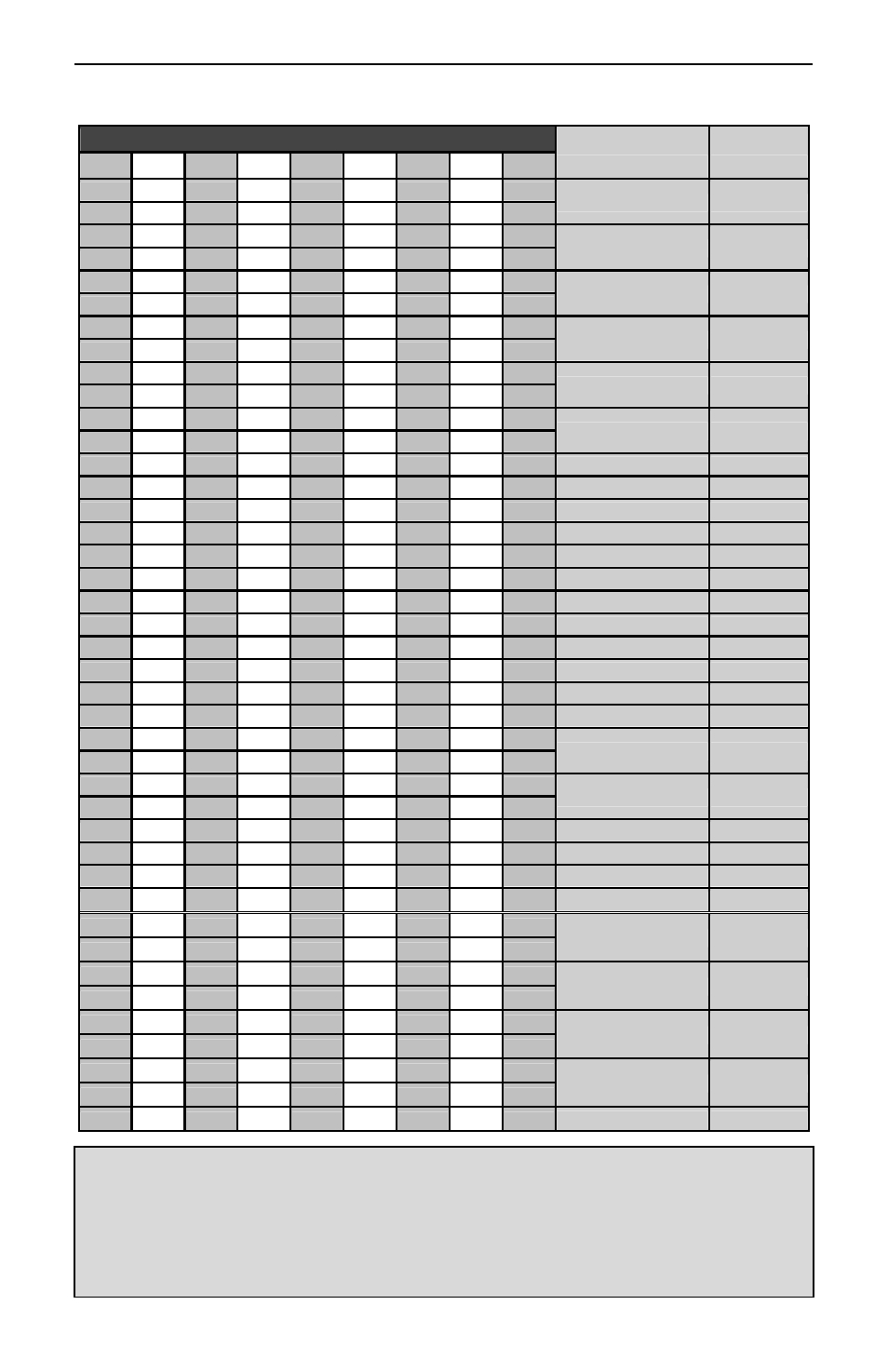
Table 5. Relay Channels Register Addresses
Address (offset from 40000)
Description
Data Type
Rly. 1 Rly. 2 Rly. 3 Rly. 4 Rly. 5 Rly. 6 Rly. 7 Rly. 8 Rly. 9
461 493 525 557 589 621 653
685
717
Alarm High Set point Floating Pt.
462 494 526 558 590 622 654
686
718
463 495 527 559 591 623 655
687
719
Alarm Low Set Point Floating Pt.
464 496 528 560 592 624 656
688
720
465 497 529 561 593 625 657
689
721
Alarm K Factor
Floating Pt.
466 498 530 562 594 626 658
690
722
467 499 531 563 595 627 659
691
723
Alarm Diff-Pressure Floating Pt.
468 500 532 564 596 628 660
692
724
469 501 533 565 597 629 661
693
725
Relay ON Time
Floating Pt.
470 502 534 566 598 630 662
694
726
471 503 535 567 599 631 663
695
727
Relay Cycles
Floating Pt.
472 504 536 568 600 632 664
696
728
473 505 537 569 601 633 665
697
729 Delay On Time
Byte
474 506 538 570 602 634 666
698
730 Delay Off Time
Byte
475 507 539 571 603 635 667
699
731 Pulse On Time
Byte
476 508 540 572 604 636 668
700
732 Pulse Off Time
Byte
477 509 541 573 605 637 669
701
733 After Flow Time
Byte
478 510 542 574 606 638 670
702
734 Alarm Type
Byte
479 511 543 575 607 639 671
703
735 Alarm Ch.
Byte
480 512 544 576 608 640 672
704
736 Alarm Sec. Ch.
Byte
481 513 545 577 609 641 673
705
737 Alarm Dig. Ch.
Byte
482 514 546 578 610 642 674
706
738 Alarm ON/OFF Flag Byte
483 515 547 579 611 643 675
707
739 Relay State Flag
Byte
484 516 548 580 612 644 676
708
740 Relay Assign Flag
Byte
485 517 549 581 613 645 677
709
741
Alarm PWM Output Floating Pt.
486 518 550 582 614 646 678
710
742
487 519 551 583 615 647 679
711
743
Alarm PID Set Pt.
Floating Pt.
488 520 552 584 616 648 680
712
744
489 521 553 585 617 649 681
713
745 Alarm PID KP Setting Integer
490 522 554 586 618 650 682
714
746 Alarm PID KI Setting Integer
491 523 555 587 619 651 683
715
747 Alarm PID I Band
Integer
492 524 556 588 620 652 684
716
748 Alarm PID Direction Byte
1351 1361 1371 1381
1391
1401
1411
1421
1431
Override Value #1* Floating Pt.
1352 1362 1372 1382
1392
1402
1412
1422
1432
1353 1363 1373 1383
1393
1403
1413
1423
1433
Override Value #2* Floating Pt.
1354 1364 1374 1384
1394
1404
1414
1424
1434
1355 1365 1375 1385
1395
1405
1415
1425
1435
Override Value #3* Floating Pt.
1356 1366 1376 1386
1396
1406
1416
1426
1436
1357 1367 1377 1387
1397
1407
1417
1427
1437
Override Value #4* Floating Pt.
1358 1368 1378 1388
1398
1408
1418
1428
1438
1359 1369 1379 1389
1399
1409
1419
1429
1439 Override Mode*
Byte
*Override Mode Byte Values:
*Override Mode Programming:
Byte Value = 0: OFF (No overrides)
Override Value #1 is the Set Point for Override.
Byte Value = 1: Input > SP with High Alarm
Override Value #2 is the High Value Alarm Set Point.
Byte Value = 2: Input > SP with Low Alarm
Override Value #3 is the Low Value Alarm Set Point.
Byte Value = 3: Input > SP with Alarm OFF
Override Value #4 is N/A.
Byte Value = 4: Input < SP with High Alarm
Byte Value = 5: Input < SP with Low Alarm
Byte Value = 6: Input < SP with Alarm OFF