Precision Digital PD941 User Manual
Page 48
ConsoliDator Multi-Channel Controller
Instruction Manual
48
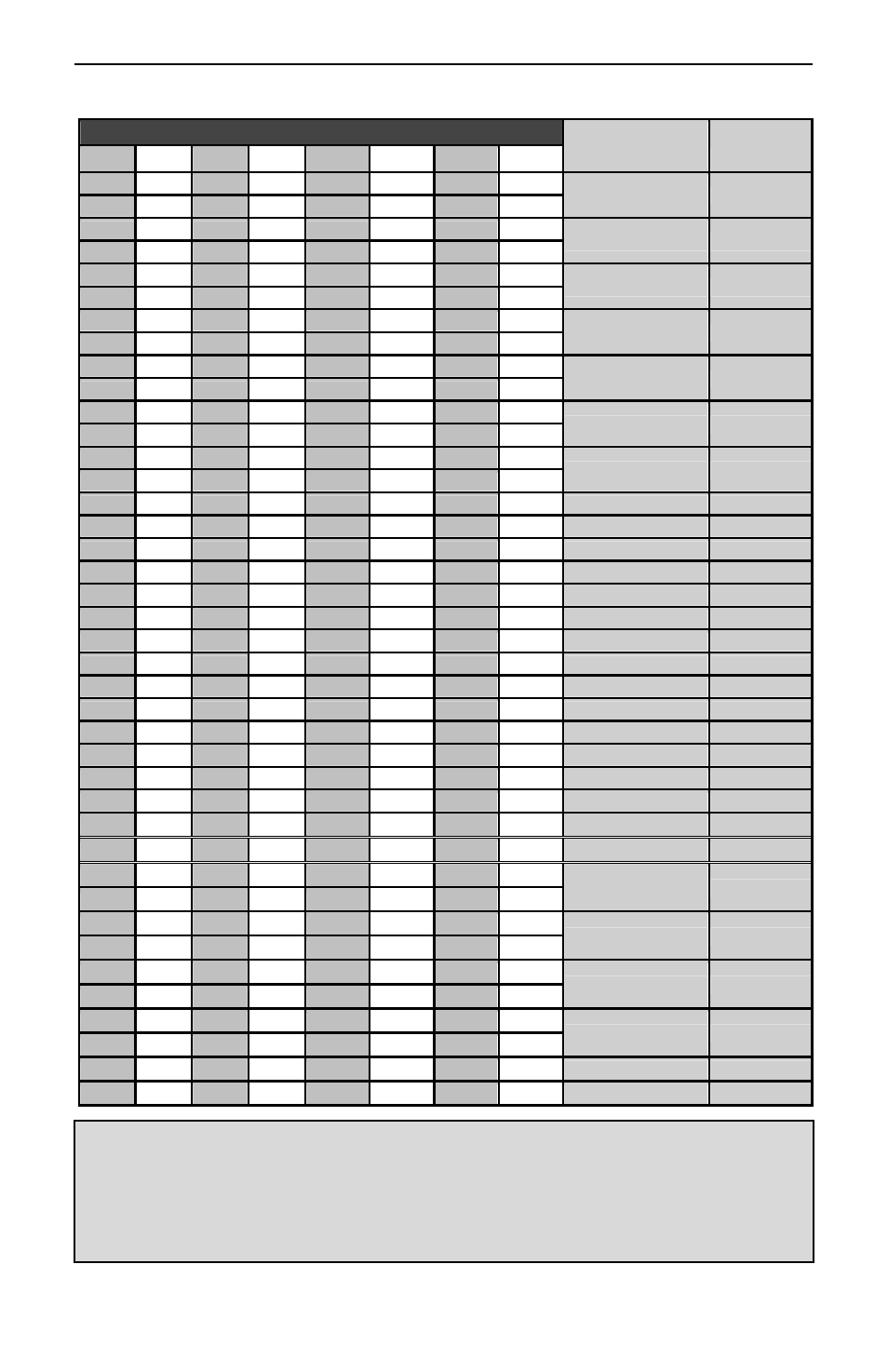
Table 2. Analog Input Channels Register Addresses
Address (offset from 40000)
Description
Data Type
Ch. 1 Ch. 2 Ch. 3 Ch. 4
Ch. 5* Ch. 6* Ch. 7* Ch. 8*
1 33 65 97 129 161 193 225
Engineering Value Floating Point
2 34 66 98 130 162 194 226
3 35 67 99 131 163 195 227
Max. Graph Value Floating Point
4 36 68 100 132 164 196 228
5 37 69 101 133 165 197 229
Min. Graph Value
Floating Point
6 38 70 102 134 166 198 230
7 39 71 103 135 167 199 231
High Value
Floating Point
8 40 72 104 136 168 200 232
9 41 73 105 137 169 201 233
High Value mA
Floating Point
10 42 74 106 138 170 202 234
11 43 75 107 139 171 203 235
Low Value
Floating Point
12 44 76 108 140 172 204 236
13 45 77 109 141 173 205 237
Low Value mA
Floating Point
14 46 78 110 142 174 206 238
15 47 79 111 143 175 207 239
Decimal Format
Byte
16 48 80 112 144 176 208 240
Ch. Online Flag
Byte
17 49 81 113 145 177 209 241
Ch. ID Char. 1
Byte
18 50 82 114 146 178 210 242
Ch. ID Char. 2
Byte
19 51 83 115 147 179 211 243
Ch. ID Char. 3
Byte
20 52 84 116 148 180 212 244
Ch. ID Char. 4
Byte
21 53 85 117 149 181 213 245
Ch. ID Char. 5
Byte
22 54 86 118 150 182 214 246
Ch. ID Char. 6
Byte
23 55 87 119 151 183 215 247
Ch. ID Char. 7
Byte
24 56 88 120 152 184 216 248
Ch. ID Char. 8
Byte
25 57 89 121 153 185 217 249
Ch. ID Char. 9
Byte
26 58 90 122 154 186 218 250
Ch. ID Char. 10
Byte
27 59 91 123 155 187 219 251
Units Character 1
Byte
28 60 92 124 156 188 220 252
Units Character 2
Byte
29 61 93 125 157 189 221 253
Units Character 3
Byte
1523 1547 1571 1595 1619 1643 1667 1691
Function Mode**
Byte
1901 1911 1921 1931 1941 1951 1961 1971
K-Factor / Modbus
Display
Floating Point
1902 1912 1922 1932 1942 1952 1962 1972
1903 1913 1923 1933 1943 1953 1963 1973
Offset
Floating Point
1904 1914 1924 1934 1944 1954 1964 1974
1905 1915 1925 1935 1945 1955 1965 1975
Conversion #1
Floating Point
1906 1916 1926 1936 1946 1956 1966 1976
1907 1917 1927 1937 1947 1957 1967 1977
Conversion #2
Floating Point
1908 1918 1928 1938 1948 1958 1968 1978
1909 1919 1929 1939 1949 1959 1969 1979
Channel Linking
Byte
1910 1920 1930 1940 1950 1960 1970 1980
Function Channel
Byte
*Channels 5-8 only apply to ConsoliDator 8 (PD980 & PD981) models.
**Function Mode Byte Values:
Byte = 0: Linear
Byte = 16: Square Root
Byte = 32: Difference
Byte = 48: Summation
Byte = 64: Exponent
Byte = 80: Multi-Point
Byte = 96: Fixed/Modbus Display Byte = 112: Integration – Sec
Byte =128: Integration – Min
Byte = 144: Integration – Hour
Byte =160: Integration – Day