Precision Digital PD941 User Manual
Page 16
ConsoliDator Multi-Channel Controller
Instruction Manual
16
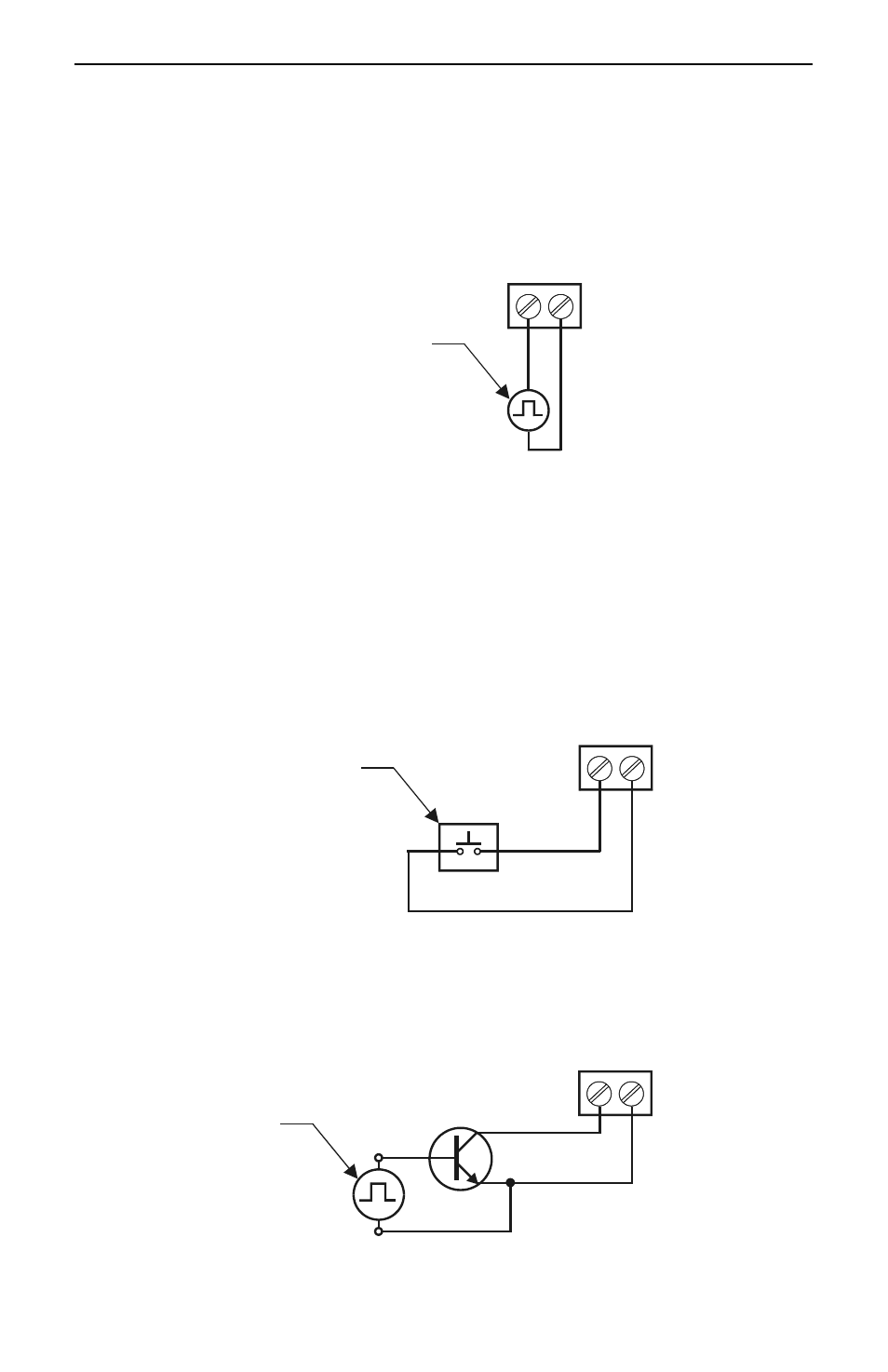
Flow Meter Pulse Input Connections
Flow Meter Pulse Inputs are wired to two-terminal connectors. A square waveform is used
in the illustration, but the input is capable of reading many other types of signals within the
voltage and frequency ranges specified.
G
+
+
Ground
Signal Source
FLOW-METER
Figure 7. Flow Meter Pulse Input Connections
Digital Input Connections
Digital Inputs are wired to two-terminal connectors. Normally open switch contacts may be
used as shown in Figure 8. Figure 9 shows a Digital Input using an NPN open collector
transistor output from a live signal. Logic LO or switch closure appearing across the
terminals is interpreted as ON. When using an open collector transistor, a logic HI at the
base (marked "B" in Figure 9) will be interpreted as ON.
G
+
Switch Contact
DIGITAL INPUT
Figure 8. Digital Input From Switch Closure
G
+
Live Signal
Source
DIGITAL INPUT
B
C
E
+
-
Figure 9. Digital Input From Live Signal