Precision Digital PD941 User Manual
Page 18
ConsoliDator Multi-Channel Controller
Instruction Manual
18
Relay Connections
Relay connections are made to three-terminal connectors labeled on the side of the case.
RELAY OUTPUT
NO - C - NC
Figure 12. Relay Connections
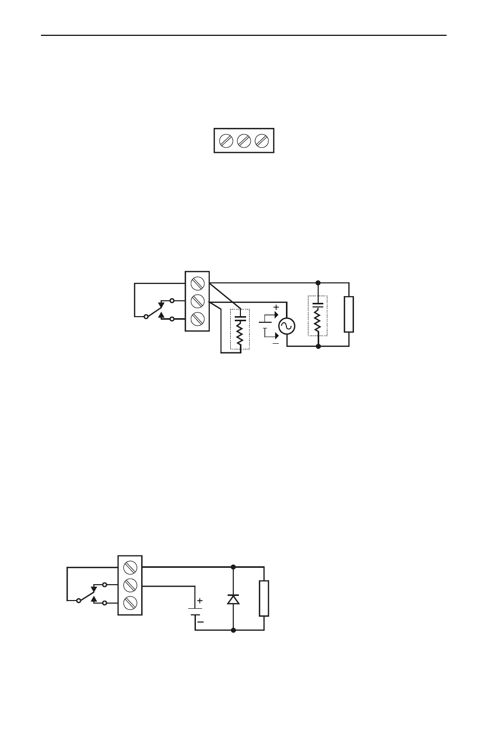
Switching Inductive Loads
The use of suppressors (snubbers) is strongly recommended when switching inductive
loads to prevent disrupting the microprocessor’s operation. The suppressors also
prolong the life of the relay contacts. Suppression can be obtained with
resistor-capacitor (RC) networks assembled by the user or purchased as complete
assemblies. Refer to the following circuits for RC network assembly and installation:
L
O
A
D
NO
C
Figure 13. AC and DC Loads Protection
Choose R and C as follows:
R: 0.5 to 1
for each volt across the contacts
C: 0.5 to 1 µF for each amp through closed contacts
Notes:
1.
Use capacitors rated for 250 VAC.
2.
RC networks may affect load release time of solenoid loads. Check to confirm
proper operation.
3.
Install the RC network at the instrument's relay screw terminals. An RC network
may also be installed across the load. Experiment for best results.
L
O
A
D
NO
C
Figure 14. Low Voltage DC Loads Protection
RC Networks Available from Precision Digital
RC networks are available from Precision Digital and should be applied to each relay
contact switching an inductive load. Part number: PDX6901.
Use diode with a reverse breakdown
voltage two to three times the circuit
voltage and forward current at least
as large as the load current.