Linear pulse width modulation mode – Precision Digital PD941 User Manual
Page 38
ConsoliDator Multi-Channel Controller
Instruction Manual
38
Linear Pulse Width
Modulation Mode
Linear PWM Mode is used to create
an on/off pulse signal with a
modulated duty cycle. In this mode
the percentage of the relay cycle in
which the relay is in the on state
varies with relation to the process
value.
See Figure 21 for an example
showing that the cycle time (period)
remains the same, but the relay-on
percentage of the cycle changes
with the process value.
Select [PWM: Linear] from Alarm
Mode options to modulate the pulse
relay signal in linear mode.
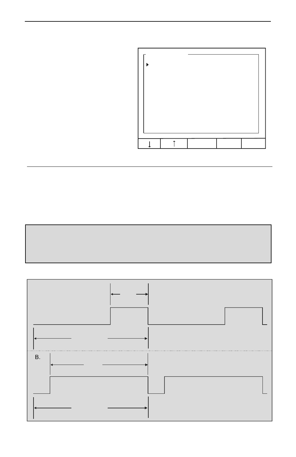
Alarm Setup: 1
Alarm Mode: PWM: Linear
Channel: [A] Flow: 1
100% Value: 16.00 GPM
0% Value: 8.00 GPM
Cycle Time: 600 sec
EDIT
EXIT
Channel
Assign the relay to any analog or pulse input.
100% Value
Enter the process value at which the pulse width will be 100% of
cycle.
0% Value
Enter the process value at which the pulse width will be 0% of
cycle.
Cycle Time
Enter the period for 1 cycle (maximum 6550 sec.)
Note 1: Due to the life expectancy of mechanical relays, it is strongly recommended that cycle times be
as long as possible (many minutes.) Using a cycle time of less than a few minutes can wear out a relay
and cause faulty operation.
Note 2: Relay is a constant OFF when process variable is at or below 10% of full span and a constant
ON when process variable is at or above 90% of full span to prevent abrupt switching from occurring and
causing damage to relays.
Cycle Time
33 %
85 %
Relay output when process variable
reaches 33% of the span specified by
and
0% Value
100% Value
Relay output when process variable
reaches 85% of the span specified by
and
0% Value
100% Value
A.
Cycle Time
Figure 21. Linear PWM Relay Timing Example