31 technical data, Inverter communication / inverter = inv, Plant monitoring – Solare Datensysteme Solar-Log User Manual
Page 214: Visualization
214
Technical Data
31 Technical Data
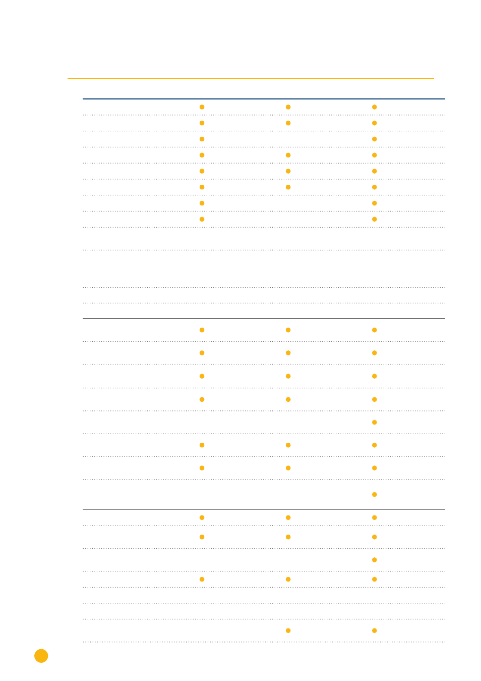
Product comparison
Solar-Log
200
Solar-Log
500
Solar-Log
1000
Inverter communication
/
inverter = INV
PM+
(2)
PM+ / WiFi
(2)
PM+ / GPRS
(2)
-
Bluetooth (BT)
(2)
WiFi (Wireless Lan)
(2)
Bluetooth (BT) / WiFi
(2)
GPRS
(2)
-
Central inverter SCB and SMB
(2)
-
Max. number of inverters (de-
pends on the INV manufacturer)
1/1 manufacturer
up to 10/1 manufacturer
up to 10/1 manufacturer
Communication interface
1 x RS485 / RS422
1 x RS485 / RS422
(1 INV manufac-
turer per bus)
1 x RS485, 2x RS485
/ RS422, 1 x CAN
(one INV manufac-
turer per bus)
recommended max. plant size
15 kWp
50 kWp
1 MWp
max. cable length
max. 1000 m
1)
max. 1000 m
1)
max. 1000 m
1)
Plant monitoring
String monitoring (depending on
type of inverter / tracker level)
Inverter failure, status of fault
and power monitoring
Sensor system connection
(irradiation/ temp./ wind)
3)
3)
E-mail and Text Mes-
sage (SMS) Alarm
Local alarm (poten-
tial-free contact)
-
-
Yield forecast and deg-
radation calculation
Self-produced energy consump-
tion: Digital electricity meter
Self-produced energy con-
sumption: Control of ext.
consumer Appliance
-
-
Visualization
Integrated Web Servers
Graphic visualization – PC
local and Internet
Graphic visualization
– USB flash drive
-
-
LED – status display
Display on the unit
-
2-line text display
full-graphic display
Controls on the device
-
Keypad
via touch screen
Large external display
RS485 / S
0
pulse
-