Solare Datensysteme Solar-Log User Manual
Page 89
89
Configuring connected devices
Section RS485-B
RS485-B is a combined interface on which an RS422 inverter can also be connected.
Here you can configure the components that are connected to this input. These components can be:
•
Inverter/Other
•
Power meters or
•
Sensors
If a wireless package is used in this bus, the wireless package button needs to be activated.
Section RS485-C (only Solar-Log 2000)
RS485-B is a combined interface on which an RS422 inverter can also be connected.
Here you can configure the components that are connected to this input. These components can be:
•
Inverters
•
Power meters or
•
Sensors
If a wireless package is used in this bus, the wireless package button needs to be activated.
Network section
If an inverter is connected to the Solar-Log™ via Network / LAN, please select the corresponding inverter
brand.
CAN (only Solar-Log 1000 and 2000)
If an inverter is connected to the Solar-Log™ via the CAN Bus, please select the corresponding inverter
brand.
Procedure
•
Define
the interface for each connected
device
•
SAVE
settings.
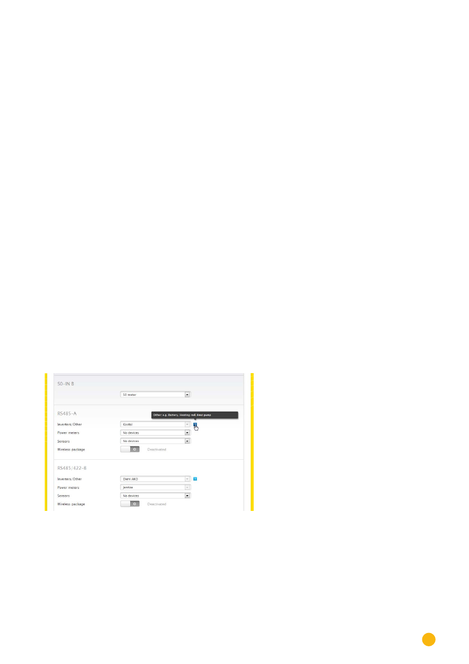
Fig.: Example of a device definition with the help text displayed
In the example, the following devices are connected:
S0 B: S0 meter
RS485 A: 1x Kostal inverter
RS485 B: 3x Diehl AKO inverters
RS485 B: 1x Janitza inverter