1 connect power, 2 connect ethernet cable, 3 apply alarm i/o – PLANET ICA-HM620 User Manual
Page 19: 4 apply audio, Connect power, Connect ethernet cable, Apply alarm i/o, Apply audio
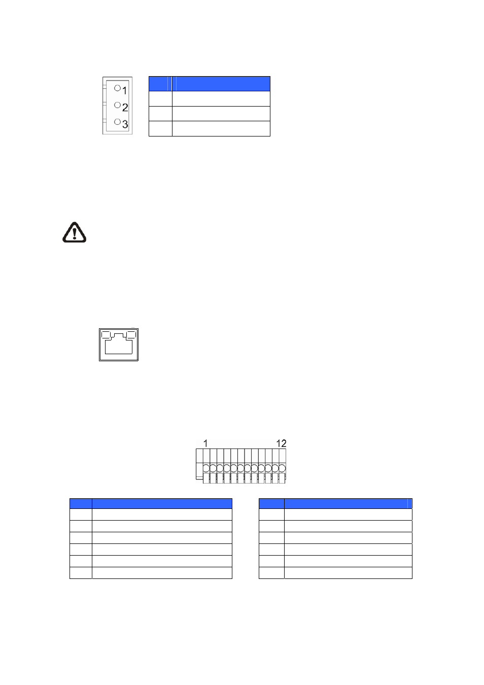
2.5.1 Connect
Power
Please refer to the illustrations below to connect power core through the supplied power adaptor.
Pin
Definition
1
AC 24_1
2
FG
3
AC 24_2
2.5.2
Connect Ethernet Cable
Use of Category 5 Ethernet cable is recommended for network connection; to have best
transmission quality, cable length shall not exceed 100 meters. Connect one end of the Ethernet cable
to the RJ-45 connector of the network Speed Dome Camera, and the other end of the cable to the
network switch or PC.
Note
NOTE: In some cases, you may need use an Ethernet crossover cable when connecting
the network Speed Dome Camera directly to the PC.
Check the status of the link indicator and activity indicator LEDs; if the LEDs are unlit, please check
LAN connection.
Green Link Light indicates good network connection.
Orange Activity Light flashes for network activity indication.
-
19
-
2.5.3 Apply
Alarm
I/O
The network Speed Dome Camera supports 4 digital alarm inputs and 2 digital alarm outputs.
Please make sure the alarm connections are properly wired before starting to configure alarm related
settings on this “Application” page. Please refer to the pin definition table below for alarm system wiring.
Pin
Definition
Pin
Definition
1
ALARM_O
ALARM_OUT_COM_2
UT_NO_1
7
2
ALARM_OUT_NC_1
8
GND
3
ALARM_OUT_COM_1
_IN_4
9
ALARM
4
GND
10
ALARM_IN_3
5
ALARM_OUT_NO_2
11
ALARM_IN_2
6
ALARM_OUT_NC_2
12
ALARM_IN_1
2.5.4 Apply
Audio
Please refer to the illustrations below to set up the audio according to the Audio pin definition.